
Smart Tweezers—also known as LCR tweezers or Smart SMD testers—have become indispensable tools in modern electronics testing. They combine the functionality of an LCR meter with a precision tweezer form factor, allowing fast, reliable measurement of tiny surface-mount components directly on a PCB or as loose parts.
For engineers, repair technicians, and quality inspectors, two of the most common and valuable measurements are capacitance (C) and equivalent series resistance (ESR). These parameters are critical for diagnosing failing capacitors, validating incoming components, and troubleshooting power integrity issues.
This article provides a comprehensive, step-by-step explanation of how to measure capacitance and ESR using Smart Tweezers, based on professional best practices applicable to tools such as Smart Tweezers ST-series, LCR Reader–type instruments, and similar devices. The principles are universal and align with industry-standard electronic test and measurement practices.
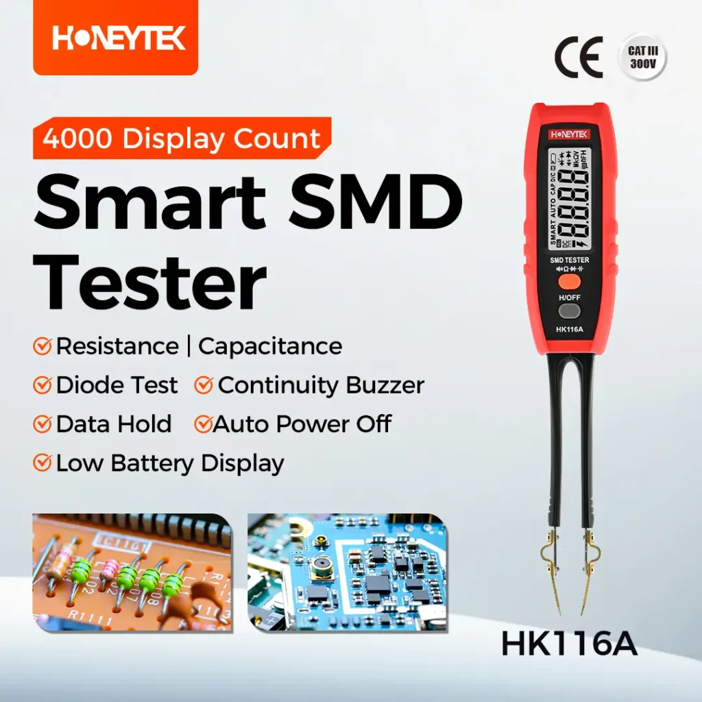
What Are Smart Tweezers?
Smart Tweezers are compact LCR measuring instruments designed specifically for SMD components. Two fine, conductive tips are integrated into a tweezer body, allowing users to clamp directly onto a component’s terminals.
Typical capabilities include:
- Automatic component identification (R / C / L)
- Auto-ranging and auto-scan measurement
- Capacitance, resistance, and often inductance measurement
- Advanced parameters such as ESR, Q, D, impedance, and phase angle (on higher-end models)
- Compact, one-hand operation for field and bench use
Compared with traditional multimeters or bench LCR meters, Smart Tweezers excel in speed, convenience, and in-circuit accessibility.
Why Measuring Capacitance and ESR Matters
Capacitance (C)
Capacitance confirms whether a capacitor still meets its nominal value. Drifted or reduced capacitance can cause:
- Increased ripple voltage
- Timing instability
- Improper filtering or decoupling
Equivalent Series Resistance (ESR)
ESR is often the earliest indicator of capacitor failure, especially for electrolytic capacitors. Elevated ESR leads to:
- Excessive heat generation
- Poor ripple current handling
- Power supply instability and noise
In many cases, ESR increases long before capacitance drops significantly, making ESR testing essential for preventive maintenance and troubleshooting.
Safety First: Before Any Measurement
Power Off and Discharge the Capacitor
Before measuring either capacitance or ESR, safety and instrument protection are mandatory.
- Ensure the circuit under test is completely powered off.
- For electrolytic or large-value capacitors, residual charge can remain even after power removal.
- Discharge the capacitor using a suitable resistor, typically 1 kΩ to 10 kΩ, across the terminals for several seconds.
Never short a capacitor directly with metal tools. Controlled discharge protects both the operator and the instrument.
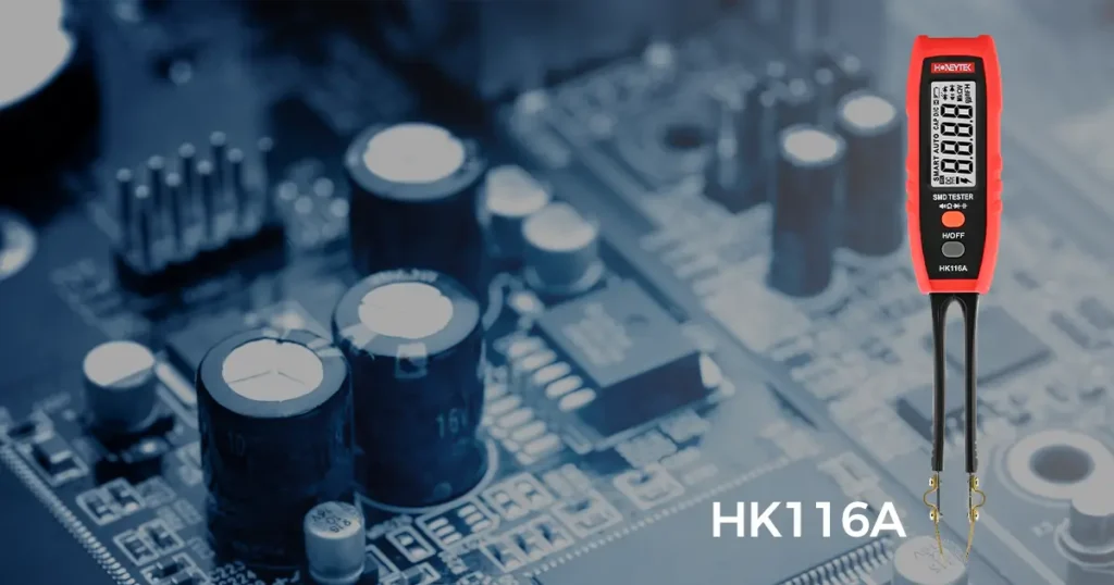
Measuring Capacitance with Smart Tweezers
Entering Capacitance Measurement Mode
Most Smart Tweezers operate in AUTO mode by default.
- Clamp the capacitor with the tweezer tips.
- The instrument automatically identifies the component as a capacitor.
- The main display switches to capacitance (C) without manual range selection.
For complex circuits or in-circuit measurements, some users prefer to force capacitance mode via the menu. This avoids misidentification caused by parallel components on the PCB.
Selecting the Correct Test Frequency
Test frequency significantly affects measurement accuracy.
- Small capacitors (nF to low µF)
Use 1 kHz or 10 kHz for stable and accurate readings. - Large electrolytic capacitors
Use 100 Hz or 120 Hz, which better represents real-world power supply conditions.
Most professional Smart Tweezers allow selection between common frequencies such as 100 Hz, 1 kHz, and 10 kHz.
Proper Clamping Technique
Accurate results depend heavily on correct physical contact.
- For SMD capacitors:
Clamp firmly on the metalized end terminals, not the ceramic body. - For through-hole or electrolytic capacitors:
Clamp directly on the leads, keeping fingers away from the metal tips.
Avoid touching the tips during measurement. Human body capacitance can significantly distort readings, especially in the pF to nF range.
Reading the Display
- The main display shows the capacitance value (e.g., 10.02 µF).
- The secondary display may show:
- Test frequency
- Equivalent circuit model (series or parallel)
- Secondary parameters such as Rs
Some instruments allow cycling through multiple display pages to view different parameters.
Measuring ESR with Smart Tweezers
Selecting ESR or Series Resistance Mode
Depending on the instrument:
- ESR may appear automatically as a secondary parameter in capacitance mode.
- Alternatively, a dedicated ESR or Rs mode can be selected from the menu.
For clarity and repeatability, using a dedicated ESR mode is recommended when available.
Choosing the Correct Frequency for ESR
ESR is frequency-dependent.
- Common practice is to measure ESR at around 100 kHz.
- This frequency better reflects the behavior of capacitors in switching power supplies and high-frequency ripple environments.
Check the instrument settings or user manual to confirm the ESR test frequency.
Discharge and Clamping Requirements
As with capacitance testing:
- Always discharge the capacitor first.
- Ensure clean, low-resistance contact between the tips and terminals.
ESR measurements are particularly sensitive to contact resistance. Oxidation, contamination, or weak clamping pressure can falsely increase ESR readings.
Interpreting ESR Results
Typical ESR values range from milliohms to a few ohms, depending on capacitor type and rating.
Evaluation methods include:
- Comparing readings with datasheet typical ESR values
- Comparing identical capacitors on the same PCB
- Identifying outliers with significantly higher ESR
A capacitor with noticeably higher ESR than its peers is often degraded or near failure.
In-Circuit Measurement
Smart Tweezers are excellent for in-circuit diagnostics, but limitations exist.
Parallel and Series Paths
When measuring on a PCB:
- Parallel capacitors increase measured capacitance
- Parallel resistive paths reduce apparent ESR
- Semiconductor junctions can distort readings
As a result, measured values may not represent a single component accurately.
Practical Diagnostic Strategy
In-circuit measurement is best used for comparative screening:
- Compare the same capacitor position across multiple boards
- Compare identical capacitors on the same board
Suspect components typically stand out clearly. For critical analysis, desoldering and off-board measurement remains the gold standard.
Tips for Improving Measurement Accuracy
Open and Short Calibration
Some Smart Tweezers support open/short calibration:
- Open calibration compensates for parasitic capacitance
- Short calibration compensates for contact resistance
Perform calibration periodically, especially before measuring small values or low ESR.
Control Environment and Handling
- Hold only the insulated part of the tweezers
- Avoid proximity to large grounded metal surfaces
- Minimize movement during measurement
These practices are especially important for low-value capacitance measurements.
Adjust Test Voltage When Available
Advanced instruments may allow selection of test voltage (e.g., 0.1 V, 0.5 V, 1.0 Vrms).
- Lower test voltage helps reduce non-linear effects
- Particularly useful for sensitive ceramic or electrolytic capacitors
Smart Tweezers vs. Other Instruments
Compared with digital multimeters, Smart Tweezers offer:
- Faster component identification
- Better contact reliability on SMD parts
- Fewer operator errors due to auto-ranging
Compared with bench LCR meters:
- Slightly lower absolute precision
- Far superior portability and in-circuit convenience
For field service, production lines, and everyday engineering tasks, Smart Tweezers provide an optimal balance.
Applications Across the Electronics Industry
- PCB repair and rework
- Incoming quality control
- Production line testing
- R&D prototyping and validation
- Electronics education and training
Manufacturers such as Honeytek, known for digital multimeters, digital clamp meters, and professional electronic measurement tools, design complementary instruments that support the same goals: accuracy, efficiency, and reliability in real-world testing.
Frequently Asked Questions
Can I measure ESR without removing the capacitor from the PCB?
Yes, but results are influenced by parallel paths. Use in-circuit ESR primarily for comparison, not absolute qualification.
Why does ESR look normal but capacitance is low?
Capacitance loss and ESR increase do not always occur simultaneously. Aging mechanisms vary by capacitor type.
Is AUTO mode reliable for all measurements?
AUTO mode works well in most cases. For complex circuits, forcing a specific mode improves consistency.
Do ceramic capacitors have ESR?
Yes, but ESR is typically very low. Measurement accuracy depends on instrument resolution and contact quality.
How often should I calibrate Smart Tweezers?
Perform open/short calibration whenever environmental conditions change or before precision measurements.
Conclusion
Smart Tweezers make capacitance and ESR testing faster, safer, and more intuitive—especially for SMD components in modern electronics. By following correct discharge procedures, selecting appropriate frequencies, and understanding in-circuit limitations, professionals can extract reliable diagnostic insights with confidence.
If you are looking to streamline electronic testing workflows, improve fault diagnosis, or enhance production efficiency, explore professional measurement solutions from Honeytek.
You May Also Be Interested In:
- True RMS Industrial Digital Multimeters: Why They Matter in Modern Electrical Systems
- Why the Honeytek HK39D Is the Ideal Compact Multimeter for Modern Field Technicians
- How Students, Vocational Schools, Home Users, and Hobbyists Should Choose a Digital Clamp Meter
- How to Choose the Right Clamp Meter for Home Appliance Repair, General Electricians
- How to Choose the Right Clamp Meter for Heavy Industry, Power Stations, Railway Engineering?
- How to Choose the Right Digital Clamp Meter for Electric Vehicle Maintenance
