

Introduction
Measuring capacitors accurately is a fundamental skill for electronics enthusiasts, technicians, and engineers. Whether you’re troubleshooting circuit boards, testing components, or performing routine maintenance, understanding how to properly use your digital multimeter’s capacitance function can save time and prevent costly mistakes.
This comprehensive guide walks you through the essential techniques for capacitor measurement, from basic setup to advanced testing methods for detecting component failures.
Understanding Capacitance and Its Units
What is Capacitance?
Capacitance refers to a component’s ability to store electrical charge at a given voltage. It represents the fundamental property that determines how much energy a capacitor can hold and release in electronic circuits.
The international unit for capacitance is the Farad (F), though most electronic components use much smaller values:
- 1 Farad (F) = 1,000 millifarads (mF) = 1,000,000 microfarads (μF)
- 1 microfarad (μF) = 1,000 nanofarads (nF) = 1,000,000 picofarads (pF)
Common Capacitor Values in Electronics
Most electronic circuits use capacitors ranging from picofarads to millifarads. Understanding these scales helps you select appropriate measurement ranges and interpret readings correctly.
How to Measure Capacitance with a Digital Multimeter

Step-by-Step Measurement Process
Step 1: Set Up Your Multimeter
- Rotate the selector dial to the capacitance position (marked with “F” or capacitor symbol)
- Ensure the multimeter is functioning properly by checking the display
Step 2: Locate the Capacitance Test Ports
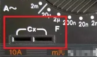
- Find the dedicated capacitance measurement sockets, typically labeled “Cx”
- These are usually located in the lower left area of the multimeter face
- The sockets are specifically designed to hold capacitor leads securely
Step 3: Insert the Capacitor
- For non-polarized capacitors: Insert leads into either socket
- For polarized capacitors (electrolytic): Pay careful attention to positive and negative terminals
- Ensure leads make solid contact within the sockets
Step 4: Read the Measurement
- Allow the multimeter to stabilize (may take several seconds for large capacitors)
- Record the displayed value and units
- Compare with the capacitor’s rated value for verification
Safety Considerations
Always discharge capacitors before testing, especially high-voltage types. Large capacitors can retain dangerous charges even when disconnected from power sources for extended periods.
Testing Capacitor Health and Performance
Method 1: Basic Functionality Test Using Analog Multimeter
When using a pointer-style analog multimeter, you can perform dynamic testing:
- Select appropriate ohm range based on capacitor size
- Discharge the capacitor completely before testing
- Touch probes to capacitor terminals and observe needle movement
- Normal behavior: Needle swings rapidly toward zero resistance, then returns to infinite resistance
- Reverse probe connection: Needle should swing further and return to original position
Interpreting Test Results
Healthy Capacitor Signs:
- Needle moves decisively and returns to infinity
- No permanent deflection toward lower resistance
- Consistent behavior when probes are reversed
Faulty Capacitor Indicators:
- Leakage: Needle doesn’t return fully to infinity position
- Open circuit: No needle movement (except for very small capacitors in pF range)
- Short circuit: Needle remains at low resistance
Advanced Leakage Testing Methods
Testing High-Value Capacitors (Above 1000μF)
For electrolytic and other large-value capacitors requiring stringent leakage specifications:
Step 1: Initial Charging Test
- Use R×10Ω range for rapid charging
- Estimate approximate capacitance during this phase
- Switch to R×1kΩ range for extended observation
Step 2: Extended Monitoring
- Observe needle position for several minutes
- Needle should remain at or very close to infinity
- Any backward movement indicates leakage current
Testing Precision Timing Capacitors
Small-value capacitors used in oscillator circuits and switching power supplies require extremely low leakage:
- Perform initial charging on R×1kΩ range
- Switch to R×10kΩ range for enhanced sensitivity
- Monitor for any needle movement – even slight deflection indicates excessive leakage
- These capacitors must show perfect infinity reading to be suitable for precision applications
Troubleshooting Common Issues
When Measurements Don’t Match Ratings

Tolerance Considerations:
- Standard capacitors typically have ±10% to ±20% tolerance
- Precision capacitors may have ±1% to ±5% tolerance
- Age and temperature can affect actual values
Environmental Factors:
- Temperature changes affect capacitance values
- Humidity can influence readings, especially for smaller values
- Allow components to reach room temperature before testing
Handling Very Small Capacitors
Capacitors in the picofarad range may not register on basic multimeter settings:
- Use the most sensitive capacitance range available
- Some meters can detect values as low as several nanofarads
- Consider specialized equipment for sub-picofarad measurements
Best Practices for Accurate Measurements
Equipment Preparation
- Calibrate your multimeter regularly
- Ensure test leads are in good condition
- Clean capacitor terminals before testing
- Use appropriate safety equipment
Measurement Techniques
- Allow sufficient settling time for readings
- Test at room temperature when possible
- Document results systematically
- Compare measurements with component specifications
Documentation and Record Keeping
Maintain detailed records of capacitor testing, especially for critical applications. Include date, environmental conditions, equipment used, and any anomalies observed.
Conclusion
Mastering capacitor measurement with digital multimeters empowers you to maintain electronic systems effectively. Whether you’re diagnosing circuit problems, verifying component specifications, or performing quality control, these techniques provide reliable methods for assessing capacitor health and performance.
Remember that capacitor testing involves both quantitative measurement and qualitative assessment. Combining numerical readings with behavioral observations during testing gives you the most complete picture of component condition.
Regular practice with these measurement techniques builds confidence and improves accuracy in electronic troubleshooting and repair work. Always prioritize safety, especially when working with high-voltage capacitors, and maintain your test equipment in proper working condition for consistent results.
