
Selecting the right digital inductance meter is not simply about buying the most expensive instrument or choosing the widest measurement range. A practical and accurate choice starts with three fundamental questions: what type of inductors you measure, at what frequency they operate, and how much accuracy your application truly requires. Once those are clear, form factor, usability, and budget become much easier decisions.
Whether you are a DIY electronics enthusiast, a power electronics engineer, or a production test technician, understanding these factors will help you avoid incorrect measurements, wasted time, and unnecessary costs.
This guide explains how digital inductance meters work, what specifications matter most, and when it makes sense to move from a handheld meter to a professional LCR instrument.
Understanding Your Application Requirements
Inductance Value and Component Type
The first step is identifying the typical inductance range you work with.
For switch-mode power supplies, DC-DC converters, and RF filtering, inductors are usually in the hundreds of nanohenries to tens of microhenries. Measuring these small values requires high resolution and stable readings, especially when tolerances are tight.
For audio circuits, motor windings, transformers, and chokes, inductance values are typically in the millihenry to henry range. In these cases, wide measurement range and repeatability matter more than ultra-high resolution.
Understanding this distinction helps prevent common mistakes, such as using a low-resolution meter to measure tiny RF inductors or over-specifying an instrument for basic applications.
Operating Frequency of the Circuit
Inductance is not a fixed value across all frequencies. Many inductors behave differently under real operating conditions due to core material, winding structure, and parasitic elements.
Low-frequency applications such as MCU circuits, analog signal conditioning, and basic power supplies usually work well with test frequencies in the hundreds of hertz to a few kilohertz.
High-frequency applications such as RF design, fast-switching power converters, and 5G-related circuits require measurements at 10 kHz, 100 kHz, or higher. Measuring an inductor at a single low frequency may produce values that differ significantly from its actual performance in the circuit.
If frequency-dependent behavior matters in your design, test frequency support becomes a critical selection factor.
Key Specifications to Evaluate
Measurement Range and Resolution
Always check both the maximum range and the minimum resolution.
A typical handheld inductance meter may cover a range such as 0.1 µH to 20 H, which is sufficient for most general electronics work. However, if your projects involve very small inductors, resolution becomes more important than maximum range.
For power electronics and RF work, a resolution of 0.1 µH or better is strongly recommended. This allows you to distinguish between similar component values and detect subtle variations.
Accuracy and Stability
Most entry-level digital inductance meters offer accuracy in the range of ±(1–2% + a few counts). This is adequate for hobbyist use, prototyping, and general development.
For component selection, quality control, or design validation, higher accuracy and better measurement stability are required. In these cases, professional LCR meters provide tighter tolerances and more consistent results.
Accuracy should always be evaluated in combination with test frequency, since a high accuracy rating at a single low frequency may not reflect real-world operating conditions.
Test Frequency Options
Basic inductance meters typically operate at a fixed internal test frequency. While convenient, this limits their usefulness for advanced designs.
Professional LCR meters support multiple selectable frequencies, such as 100 Hz, 1 kHz, 10 kHz, and sometimes 100 kHz or higher. This capability allows engineers to evaluate inductors under conditions closer to actual application environments.
If your work involves switching power supplies, RF circuits, or precision filtering, multi-frequency testing is highly recommended.
Instrument Form Factor and Price Levels
Handheld Digital Inductance Meters
Handheld inductance meters are compact, portable, and easy to use. They are ideal for bench work, field service, and educational environments.
Advantages
- Affordable entry cost
- Simple operation
- Portable and battery powered
- Suitable for single-component measurements
Limitations
- Fixed or limited test frequency
- Limited advanced parameters
- Reduced accuracy for very small or high-frequency inductors
These meters are best suited for DIY electronics, basic power designs, and routine troubleshooting.
Bench-Top LCR Meters
Bench-top LCR meters, also known as digital bridges, are professional instruments designed for accuracy and repeatability.
Advantages
- Multiple test frequencies
- Measurement of L, C, R, Q, D, and ESR
- Higher accuracy and stability
- Support for fixtures and four-wire measurement
Limitations
- Higher cost
- Larger footprint
- Less portable
They are widely used in R&D labs, production lines, and component qualification workflows.
Practical Selection Recommendations
For Hobbyists and General Electronics Projects
If your projects focus on microcontrollers, simple power supplies, and general circuit development, a handheld digital inductance meter with the following features is usually sufficient:
- Measurement range covering at least 0.1 µH to 20 H
- Accuracy around ±1–2%
- Auto-range functionality
- Stable display and data hold
- Compact and durable design
This type of instrument balances cost, usability, and performance for most non-specialized applications.
For Professional Power and RF Design
If you are developing switch-mode power supplies, motors, transformers, or RF circuits, a bench-top LCR meter is the better long-term investment.
Key features to prioritize include:
- Multiple selectable test frequencies
- Measurement of L, C, R, Q, D, and ESR
- Fixture support for repeatable results
- High measurement stability and traceability
Although the initial cost is higher, the accuracy and insight gained during design and validation often justify the investment.
Common Measurement Pitfalls to Avoid
Many inaccurate inductance readings are caused not by the instrument, but by incorrect usage.
- Always zero or compensate test leads before measuring small inductors.
- Keep test leads short to reduce parasitic inductance.
- Avoid measuring inductors while they are still soldered into complex circuits.
- Ensure the test frequency aligns with your application.
Understanding these basics can significantly improve measurement reliability.
Frequently Asked Questions
What is the difference between an inductance meter and an LCR meter?
An inductance meter measures inductance only, typically at a fixed frequency. An LCR meter measures inductance, capacitance, and resistance, often at multiple test frequencies, and provides additional parameters such as Q and D.
Is a handheld inductance meter accurate enough for power supply design?
For basic designs and prototyping, yes. For optimization, component comparison, and production validation, a multi-frequency LCR meter is more suitable.
Why do inductance values change with frequency?
Inductors contain core materials and parasitic elements that respond differently at different frequencies. Measuring at a frequency close to the actual operating condition provides more meaningful results.
Can a digital multimeter measure inductance?
Some digital multimeters include inductance measurement, but accuracy and resolution are usually limited. Dedicated inductance meters or LCR instruments offer better performance.
How important is test lead compensation?
Extremely important when measuring small inductors. Uncompensated test leads can introduce errors larger than the component being measured.
Choosing a Reliable Measurement Tool Manufacturer
Recommended Products Based on Application Needs
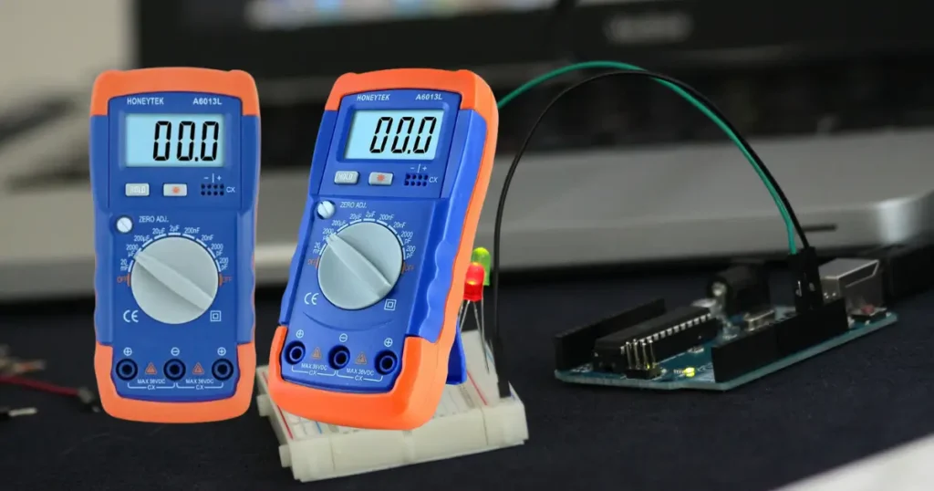
When selecting a measurement tool manufacturer, it is not enough to look only at brand reputation. The product lineup must also demonstrate clear positioning, transparent specifications, and practical differentiation for real-world electronic testing scenarios. Based on the requirements discussed above, the following products illustrated in the image are strong examples of how Honeytek structures its component measurement solutions.
Pocket Capacitance Meters for Daily Electronics Work
For engineers, technicians, and electronics hobbyists who frequently test discrete capacitors during development, maintenance, or incoming inspection, a dedicated pocket capacitance meter offers faster and more reliable results than a general-purpose multimeter.
Both the A6013L and HK39L are compact, 2000-count capacitance meters designed specifically for this role.
Looking to expand your test equipment lineup or source reliable component measurement tools for your business or lab?
Contact Honeytek to learn more about these capacitance meters, request technical documentation, or discuss OEM and bulk supply options.
You May Also Be Interested In:
- True RMS Industrial Digital Multimeters: Why They Matter in Modern Electrical Systems
- Why the Honeytek HK39D Is the Ideal Compact Multimeter for Modern Field Technicians
- How Students, Vocational Schools, Home Users, and Hobbyists Should Choose a Digital Clamp Meter
- How to Choose the Right Clamp Meter for Home Appliance Repair, General Electricians
- How to Choose the Right Clamp Meter for Heavy Industry, Power Stations, Railway Engineering?
- How to Choose the Right Digital Clamp Meter for Electric Vehicle Maintenance
