
Electric motors power countless machines in industries, homes, and vehicles. However, motors can fail due to insulation breakdown, short circuits, winding damage, or bearing issues. Knowing how to test a motor with a multimeter allows technicians and electricians to quickly identify faults, prevent downtime, and ensure safety.
In this guide, we’ll explain how to check the condition of AC motors, single-phase motors, DC motors, fan motors, and even dual-speed motors using a multimeter, insulation tester (megger), and simple diagnostic methods.
Why Test Motors with a Multimeter?
A multimeter is one of the most versatile diagnostic tools. It can:
- Measure resistance to check winding balance
- Test continuity to find broken connections
- Measure insulation resistance (with a megger) to detect ground faults
- Help diagnose capacitor conditions in single-phase motors
With just a multimeter, you can detect:
- Ground faults (motor shorted to casing)
- Open circuits (broken winding or lead)
- Phase imbalance (uneven winding resistance)
- Capacitor failure in single-phase motors

1. Testing Three-Phase AC Motors
Step 1: Insulation Resistance Test
- Use a 500V insulation tester (megger).
- Connect one probe to the motor frame (ground) and the other to each winding terminal (U, V, W).
- A healthy motor should show >0.5 MΩ. Lower values indicate moisture or insulation breakdown.
Step 2: Phase Resistance Balance
- Use a multimeter on the ohm (Ω) range.
- Measure between A-B, B-C, and C-A.
- The resistance values should be nearly equal. Large deviations suggest a winding fault.
Step 3: Mechanical Inspection
- Rotate the shaft manually. It should turn smoothly without grinding or unusual noise.
- Check bearings and cooling fan for wear.
Step 4: Load Test
- Compare actual running current with nameplate values.
- Current imbalance >10% may indicate winding problems.
2. Testing Single-Phase Motors

Single-phase motors often include a start capacitor. Testing involves both the windings and the capacitor.
Step 1: Insulation Test
- Use a 500V megger.
- Insulation resistance between winding and casing should be ≥0.5 MΩ.
Step 2: Winding Continuity
- Use a multimeter.
- Measure resistance between leads.
- The start winding usually has higher resistance than the run winding.
Step 3: Capacitor Test
- Set analog multimeter to 1KΩ or 10KΩ range.
- Connect probes across the capacitor terminals.
- A good capacitor will show a quick deflection and return.
- If the needle stays right → capacitor shorted.
- If no movement → capacitor open or failed.
3. Testing DC Motors
DC motors can be brushed or brushless.
Step 1: Continuity Test
- Use a multimeter to check for open windings.
- Resistance should be low but not zero.
Step 2: Output Voltage Check
- Rotate the shaft while measuring voltage at output terminals.
- Brushed DC motor: expect DC voltage.
- Brushless DC motor (3-phase): expect AC voltage proportional to speed.
Step 3: Static Inspection
- Check commutator surface for wear or burns.
- Inspect brushes for cracks, wear, or poor contact.
Step 4: Dynamic Test
- Measure no-load current: should be <10% of rated current.
- Abnormally high current → shorted windings or friction.
4. Testing Idle (Stored) Motors
For motors stored for months:
- Measure resistance between windings: balanced within 2%.
- Insulation resistance should be >0.5 MΩ (or >5 MΩ for high-voltage motors).
- If resistance is <0.5 MΩ → motor needs drying.
Rotate rotor manually: should turn freely without scraping.
5. Testing Fan Motors
Fan motors often have multiple windings for different speeds.
Step 1: Identify Leads
- Typical wires: 3 speed leads (low, medium, high) + 2 capacitor leads.
Step 2: Resistance Measurement
- Measure resistance between capacitor wire and each speed wire.
- Higher resistance corresponds to higher fan speed.
- If one speed winding reads open circuit, that winding is damaged.
Step 3: Ground Test
- Check resistance between any lead and motor casing.
- Should be infinite (open). Any continuity means ground fault.
6. Testing Dual-Speed Motors
Dual-speed (two-winding) motors require:
- Measuring resistance of primary and secondary windings.
- All three windings per set (U1, V1, W1 and U2, V2, W2) should be balanced.
- Insulation resistance should exceed 5 MΩ.
Common Motor Testing FAQs
Q1: What insulation resistance is acceptable for motors?
For low-voltage motors, >0.5 MΩ is acceptable. For critical applications, >2 MΩ is preferred.
Q2: Can I test motor windings without a megger?
Yes, but accuracy is limited. A digital multimeter can detect open or shorted windings but may miss minor insulation failures.
Q3: Why does my motor show almost 0Ω resistance between windings?
Large motors (>15 kW) may have very low resistance that appears as 0Ω on a standard multimeter. Use a micro-ohmmeter for accurate measurement.
Q4: How do I know if my motor capacitor is faulty?
If the motor hums but does not start, or if the multimeter shows no deflection when testing, the capacitor may be faulty.
Q5: Can a motor fail due to mechanical issues alone?
Yes. Worn bearings, blocked fans, or seized shafts can overload and burn out windings.
Safety Precautions When Testing Motors
- Always disconnect power before testing.
- Discharge capacitors before handling.
- Use appropriate rated insulation testers.
- Do not touch live terminals during running current tests.
Conclusion
Testing a motor with a multimeter helps identify winding faults, insulation failures, and capacitor issues quickly. For industrial technicians, combining a multimeter with a megger and micro-ohmmeter ensures the most accurate results.
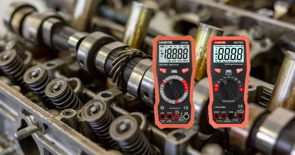
Honeytek, as a trusted manufacturer of digital multimeters and test equipment, provides professional tools designed for technicians, electricians, and engineers worldwide. Whether diagnosing motors, testing circuits, or performing preventive maintenance, Honeytek instruments deliver reliability and precision.
Looking for a professional-grade multimeter for motor diagnostics?
Explore Honeytek’s range of advanced multimeters today and make motor testing faster, safer, and more accurate.

