
Temperature is one of the fastest indicators of HVAC system performance. An unexpected hot spot on a condenser, a warm section of supply duct, or a temperature difference between two similar registers can help an HVAC technician narrow down a problem before opening equipment or performing more invasive tests.
An HVAC infrared thermometer makes this initial inspection fast and non-contact. It allows technicians to scan duct surfaces, registers, coils, motors, pipes, and other HVAC components from a safe working distance.
However, an infrared thermometer does not measure air temperature directly. It measures the infrared energy emitted by a surface and converts that energy into a temperature reading. For this reason, good measurement technique—and knowing when to confirm a reading with another instrument—is essential.
This guide explains how to use an infrared thermometer for HVAC temperature measurement, including:
- Ductwork inspection and suspected duct leak detection
- Condenser and outdoor-unit troubleshooting
- Supply and return register comparison
- Basic HVAC temperature balance surveys
- Selecting the right Honeytek infrared thermometer
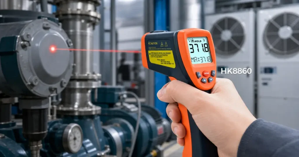
What Can an Infrared Thermometer Measure in an HVAC System?
An infrared thermometer measures surface temperature without physically touching the target. Common HVAC measurement points include:
- Supply and return air registers
- Exposed ductwork and duct insulation jackets
- Duct joints, seams, elbows, and branches
- Condenser coil surfaces
- Compressor and fan motor housings
- Refrigerant-line surfaces
- Valves, pumps, bearings, and electrical enclosures
- Boiler and hydronic-system components
Because it responds quickly, an IR thermometer is especially useful for comparing multiple components and identifying an unusual temperature pattern.
For example, a technician may scan ten supply registers and find that one register surface is noticeably warmer than the others. That result does not identify the fault by itself, but it provides a useful location for additional airflow, duct, and air-temperature tests.
Important: Surface Temperature Is Not Air Temperature
An infrared thermometer pointed at a supply register measures the surface temperature of the register, not the temperature of the air moving through it.
Register surface temperature may be affected by:
- The register material and finish
- Room temperature
- Supply-air temperature
- Air velocity
- Measurement distance
- Nearby surfaces
- Sunlight or other heat sources
Use an IR thermometer for rapid comparisons and surface-temperature screening. Use an insertion probe, thermistor, thermocouple, or other suitable air probe when an accurate supply-to-return air temperature difference is required.
Similarly, an infrared thermometer can help identify suspicious temperature patterns around duct joints, but a temperature anomaly alone does not prove that a duct is leaking. Confirm suspected leakage with an appropriate method, such as a smoke test, pressure test, calibrated duct leakage tester, or physical inspection.
Before You Start: Prepare for Accurate HVAC Temperature Measurement
Reliable HVAC troubleshooting depends on repeatable measurement conditions. Before taking readings, complete the following checks.
1. Allow the HVAC System to Stabilize
Confirm that the system is operating in the required heating or cooling mode. Record:
- Thermostat setting
- Fan operating mode
- Indoor temperature
- Outdoor temperature
- Equipment operating stage
- Register and damper positions
- Relevant weather conditions
Allow the equipment to reach a reasonably stable operating condition in accordance with the system type and manufacturer’s service procedure.
Avoid comparing a reading taken immediately after startup with one taken after prolonged operation.
2. Allow the Infrared Thermometer to Acclimate
Moving an infrared thermometer from a cold service vehicle into a warm mechanical room—or from a warm building into cold outdoor conditions—can temporarily affect its readings.
Allow the instrument to acclimate to the new environment before making critical comparisons. The required time depends on the temperature change and the instrument manufacturer’s instructions.
3. Inspect the Target Surface
Check whether the surface is:
- Wet or covered with condensation
- Frosted or iced
- Highly polished
- Exposed to direct sunlight
- Smaller than the thermometer’s measurement spot
- Affected by another nearby hot or cold object
Water, frost, reflective metal, and external radiation can all produce misleading results.
4. Verify the Distance-to-Spot Ratio
The distance-to-spot ratio, or D:S ratio, describes the relationship between the distance from the instrument to the target and the approximate diameter of the measured area.
With a 12:1 D:S ratio, for example, a measurement taken from 12 inches away covers a spot approximately 1 inch in diameter.
The target should be larger than the entire measurement spot. When inspecting a small pipe, valve, duct seam, or motor bearing area, move close enough to prevent the instrument from averaging the target with surrounding surfaces.
The laser is primarily an aiming aid. It does not necessarily show the full size of the measurement area.
5. Account for Emissivity
Emissivity describes how effectively a surface emits infrared energy. Painted, oxidized, rubber, insulation, and many nonmetallic surfaces are generally easier to measure than polished metals.
Shiny aluminum, stainless steel, and copper can reflect infrared energy from surrounding objects. The resulting temperature may appear higher or lower than the actual surface temperature.
For reflective HVAC surfaces:
- Use an infrared thermometer with adjustable emissivity.
- Refer to the instrument instructions and an appropriate emissivity reference.
- Measure a painted or oxidized section when available.
- Apply matte black tape to a safe, clean measurement point and allow it to reach the surface temperature.
- Confirm critical pipe readings with a contact clamp or surface probe.
Do not apply tape to moving, electrically unsafe, extremely hot, contaminated, or inaccessible components.
How to Inspect HVAC Ductwork with an Infrared Thermometer
Infrared thermometers are useful for finding surface-temperature changes along exposed ductwork. These changes can indicate areas that require closer inspection for air leakage, damaged insulation, thermal bridging, or unwanted heat gain.
Step-by-Step Duct Inspection Procedure
- Identify the duct route.
Locate the supply trunk, return duct, branches, elbows, transitions, dampers, joints, and areas that pass through unconditioned spaces. - Establish a baseline.
Take the first reading near the air-handling unit on a consistent surface material. Record the system mode and ambient temperature. - Scan along the duct.
Measure the surface at consistent intervals. Keep the distance, angle, and measurement position as uniform as possible. - Check vulnerable locations.
Take additional readings at seams, joints, takeoffs, elbows, access doors, supports, insulation terminations, and wall or ceiling penetrations. - Compare nearby surfaces.
Look for sudden changes instead of relying on a single temperature value. - Mark suspicious areas.
Record the location and temperature. Take a photograph when possible. - Inspect the insulation.
Look for loose jackets, compressed insulation, missing sections, moisture, damaged vapor barriers, or exposed metal. - Verify the suspected fault.
Use a smoke pencil, pressure measurement, duct leakage test, or physical inspection to determine whether leakage is present. - Retest after repair.
Repeat the measurement under similar system and environmental conditions.
Temperature Patterns That May Indicate a Duct Problem
During cooling operation, a localized warm area on a cool supply duct may indicate:
- Missing or damaged insulation
- Heat gain from an unconditioned space
- A thermal bridge
- A poorly sealed joint
- Moisture in the insulation
- A nearby heat source
During heating operation, a localized cool area may indicate similar insulation or leakage problems.
The shape of the anomaly can also provide useful clues:
- A sharp change around a joint may justify a leakage inspection.
- A large, continuous temperature change may indicate insulation damage.
- A narrow repeating pattern may correspond to supports or metal fasteners.
- An unusual reading on shiny duct metal may simply be infrared reflection.
Infrared scanning is therefore a duct leak detection screening method, not a quantitative leakage test. A calibrated duct leakage tester is required when the objective is to measure airtightness or leakage rate.
How to Check a Condenser with an Infrared Thermometer
An outdoor condenser contains moving fans, electrical components, hot surfaces, and pressurized refrigerant. Follow the manufacturer’s service instructions and applicable electrical and mechanical safety procedures.
Do not remove protective guards or reach into operating equipment to obtain an infrared reading.
Step-by-Step Condenser Inspection
- Record outdoor conditions.
Note outdoor air temperature, weather, direct sunlight, and equipment operating mode. - Perform a visual inspection.
Check for blocked airflow, dirt, leaves, bent fins, damaged guards, and inadequate clearance around the unit. - Confirm operating status.
Observe whether the condenser fan and compressor appear to be operating normally. - Allow operation to stabilize.
Avoid diagnosing the system from an isolated startup reading. - Create a measurement pattern.
Scan equivalent areas across the condenser coil—such as the top, middle, bottom, left, and right sections. - Keep technique consistent.
Use approximately the same distance and angle at every measurement point. - Compare coil regions.
Look for an unusual section rather than assuming the entire coil should have one uniform surface temperature. - Check accessible equipment housings.
Scan the fan motor housing, compressor shell, and other safe external surfaces for abnormal hot spots or changing temperature trends. - Inspect refrigerant-line surfaces carefully.
Reflective copper tubing may produce unreliable infrared readings. Use matte tape or a contact clamp probe for critical measurements. - Confirm the diagnosis with appropriate instruments.
Use refrigerant pressure and temperature instruments, electrical meters, airflow tools, and manufacturer performance data as required.
What an Abnormal Condenser Temperature Pattern May Mean
| Observation | Possible explanation | Recommended follow-up |
|---|---|---|
| One coil section differs substantially from surrounding sections | Restricted airflow, dirt, physical obstruction, reflection, or refrigerant-distribution issue | Inspect and clean the coil; confirm with contact temperature and system measurements |
| Fan motor housing temperature continues to rise | Motor loading, bearing, airflow, or electrical problem | Check current, voltage, bearing condition, and manufacturer limits |
| Compressor shell appears unusually hot | High load, poor heat rejection, electrical issue, or measurement error | Follow the manufacturer’s diagnostic procedure |
| Refrigerant-line reading changes when the angle changes | Infrared reflection from shiny copper | Apply matte tape or use a contact clamp probe |
| Coil readings differ between sunny and shaded areas | Solar loading | Repeat under controlled or comparable conditions |
An IR thermometer cannot determine refrigerant charge from a surface reading alone. Superheat, subcooling, pressures, airflow, system design, and operating conditions must be evaluated using the appropriate service procedure.
How to Check Supply and Return Vents
A quick register survey can help locate rooms or branches that require a more detailed HVAC temperature measurement or airflow test.
Step-by-Step Register Temperature Survey
- Set the system to the required operating mode.
- Confirm that registers and intended balancing dampers are in their test positions.
- Assign an identification number to each supply and return register.
- Select a repeatable measurement point on each grille.
- Measure the same type of surface from a consistent distance and angle.
- Record the register surface temperature and room temperature.
- Compare registers served by similar branches or zones.
- Identify registers that differ significantly from comparable locations.
- Measure actual air temperature with an appropriate air probe.
- Check air velocity or volume with an anemometer or flow hood.
- Inspect the associated duct branch if the result remains abnormal.
- Repeat the survey after adjustment or repair.
Temperature Balance Is Not Airflow Balance
An infrared thermometer can help identify uneven temperature distribution, but it cannot measure airflow.
A room may be too warm because of:
- Low supply airflow
- Duct leakage
- Poor duct insulation
- Incorrect damper position
- Dirty filters or coils
- High system static pressure
- Solar gain
- Inadequate return-air paths
- Building-envelope leakage
- Incorrect equipment operation
- A room load that exceeds the original design assumption
Use a flow hood or anemometer when actual airflow balance is required. For formal testing, adjusting, and balancing work, follow the applicable project specification and recognized TAB procedure.
How to Interpret HVAC Temperature Differences
A temperature difference is most useful when the two readings are:
- Taken under the same operating conditions
- Measured with the same instrument
- Taken on comparable surface materials
- Collected from clearly defined locations
- Repeated using the same distance and angle
Avoid applying one universal “correct” temperature difference to every HVAC system. Expected values vary with equipment type, load, humidity, airflow, controls, refrigerant conditions, and manufacturer requirements.
A better troubleshooting method is to:
- Compare the readings with equipment documentation.
- Compare similar components or zones.
- Confirm the result with a contact or air probe.
- Evaluate airflow, pressure, electrical, and refrigerant data.
- Document the result before and after corrective work.
Common HVAC Infrared Thermometer Mistakes
Measuring from Too Far Away
If the measurement spot is larger than the target, the reading may include the wall, ceiling, adjacent pipe, or background surface.
Pointing at Shiny Metal
Polished copper and aluminum may reflect nearby people, equipment, sunlight, or hot surfaces. A stable display does not guarantee an accurate reading.
Treating the Laser as the Temperature Sensor
The laser helps with aiming. The infrared detector measures a larger area that depends on the instrument’s optical ratio.
Treating Register Temperature as Air Temperature
A grille can be warmer or cooler than the air flowing through it. Use an air probe when actual supply or return air temperature is required.
Comparing Different Operating Conditions
A measurement taken on a cool morning cannot always be compared directly with one taken during peak afternoon load.
Diagnosing from One Reading
Use reference points, repeat measurements, trends, and verification tools. One surface temperature rarely identifies the root cause of an HVAC fault.
Recommended Honeytek Infrared Thermometers for HVAC Work
Honeytek offers several non-contact infrared thermometers suitable for HVAC surface inspection. The best model depends on the surfaces being measured and the required working range.
Honeytek HK8861: Recommended for Mixed HVAC Surfaces
The Honeytek HK8861 is the most versatile option among the models shown for technicians who frequently inspect different HVAC surface materials.
Key specifications include:
- Temperature range: −32°C to 350°C (−26°F to 662°F)
- Adjustable emissivity: 0.10 to 1.00
- Distance-to-spot ratio: 10:1
- Resolution: 0.1°C/0.1°F
- Response time: approximately 0.1 second
- Backlight
- Automatic data hold
- Maximum/minimum display
- Low-battery indication
Its adjustable emissivity is particularly useful when moving between painted ductwork, insulation jackets, oxidized components, and other surfaces with different emissivity characteristics.
For critical measurements on shiny copper or aluminum, the reading should still be verified with matte tape or a contact probe.
Honeytek HK8860: A Practical Choice for Routine Screening
The Honeytek HK8860 has the same listed temperature range, 10:1 D:S ratio, 0.1°C/0.1°F resolution, and fast response as the HK8861, but its emissivity is fixed at 0.95.
It is suited to routine comparative inspection of higher-emissivity surfaces such as:
- Painted ductwork
- Many insulation jackets
- Rubber components
- Non-reflective housings
- Prepared surfaces with matte tape
The fixed-emissivity design is straightforward for technicians who mainly perform quick surface checks on similar materials.
Honeytek HK8866: Recommended for Wider Temperature Coverage and Longer Reach
The Honeytek HK8866 provides:
- Temperature range: −50°C to 600°C (−58°F to 1112°F)
- Distance-to-spot ratio: 12:1
- Fixed emissivity: 0.95
- Resolution: 0.1°C/0.1°F
- Response time: approximately 0.1 second
- Automatic data hold
- Maximum/minimum display
- Backlight
- Low-battery indication
- Compact 135 g body
Its wider range and 12:1 optical ratio make it a suitable option for broader HVAC and industrial maintenance work, including equipment housings and surfaces that are difficult to approach closely.
Because the emissivity is fixed at 0.95, reflective surfaces should be prepared or verified with a contact measurement.
Which Honeytek Model Should You Choose?
| Model | Temperature range | Emissivity | D:S ratio | Best suited to |
|---|---|---|---|---|
| HK8860 | −32°C to 350°C | Fixed at 0.95 | 10:1 | Routine HVAC screening on non-reflective surfaces |
| HK8861 | −32°C to 350°C | Adjustable, 0.10–1.00 | 10:1 | Professional HVAC work involving varied surface materials |
| HK8866 | −50°C to 600°C | Fixed at 0.95 | 12:1 | Wider-temperature applications and relatively smaller targets at distance |
For general HVAC contractors, the HK8861 is the strongest all-around recommendation because adjustable emissivity provides greater flexibility across different materials. Choose the HK8866 when a wider measurement range or 12:1 D:S ratio is more important.
Product specifications should be confirmed on the applicable product page, datasheet, or quotation before purchase.
Document Every HVAC Inspection
A professional HVAC temperature report should record:
- Customer or site name
- Equipment identification
- Date and time
- Technician’s name
- Instrument model
- Instrument verification or calibration status
- Emissivity setting
- Measurement distance
- Target surface and material
- System operating mode
- Indoor and outdoor conditions
- Supply and return readings
- Suspected fault
- Verification method
- Corrective action
- Before-and-after results
A measurement history helps technicians identify trends, demonstrate the reason for a repair, and verify whether corrective work produced a measurable improvement.
HVAC Infrared Thermometer Inspection Checklist
Before completing the inspection, confirm that you have:
- Allowed the HVAC system to stabilize
- Allowed the thermometer to acclimate
- Checked the target material and emissivity
- Used the correct distance for the D:S ratio
- Avoided direct measurement of reflective metal where possible
- Measured comparable points consistently
- Checked ducts, registers, coils, and equipment housings
- Used an air probe for actual air temperature
- Used an airflow instrument for balancing
- Confirmed suspected duct leakage
- Documented the operating conditions
- Repeated measurements after repair
Frequently Asked Questions
Can an infrared thermometer measure the air temperature coming from an HVAC vent?
Not directly. An infrared thermometer measures the vent or register surface. Use an appropriate air-temperature probe when the actual supply-air temperature is required.
Can an infrared thermometer find a duct leak?
It can identify surface-temperature patterns that suggest where leakage or insulation damage may be present. It cannot measure duct airtightness or confirm leakage by itself.
What is the best infrared thermometer for HVAC contractors?
For the Honeytek models compared here, the HK8861 is the most flexible option because it combines a −32°C to 350°C range with adjustable emissivity. The best choice still depends on the target materials, required temperature range, optical ratio, and work environment.
Why does my infrared reading change on a copper pipe?
Clean or polished copper has low emissivity and reflects infrared energy from its surroundings. Use matte tape at a safe measurement point or confirm the temperature with a contact clamp probe.
Can an infrared thermometer balance an HVAC system?
It can support a temperature distribution survey, but it cannot balance airflow. Use a flow hood, anemometer, manometer, and the appropriate TAB procedure.
Conclusion
An HVAC infrared thermometer helps technicians scan components quickly, compare surface temperatures, and locate areas that require further investigation. It is especially useful for duct inspections, condenser surveys, register comparisons, motor checks, and preventive maintenance.
Accurate results depend on correct distance, emissivity, target size, surface condition, system stability, and repeatable technique. Most importantly, infrared readings should be treated as diagnostic evidence—not as a complete diagnosis.
For contractors working with varied HVAC materials, the Honeytek HK8861 offers adjustable emissivity and fast surface-temperature measurement. The HK8860 provides a straightforward option for routine inspections, while the HK8866 offers wider temperature coverage and a 12:1 distance-to-spot ratio.
Used alongside contact probes, airflow instruments, electrical meters, pressure tools, manufacturer data, and professional judgment, an infrared thermometer can help HVAC technicians troubleshoot faster and document their work more effectively.
You might be interested in:
- Infrared Thermometer Measurement Principles and Error Sources Explained
- Consumer vs Industrial Infrared Thermometers: A Practical Buying Guide
- Infrared Thermometers in Medical Screening: Standards & Best Practices
- Thermal Imagers vs. Infrared Thermometers: Differences, Principles, and Applications
- Application of Honeytek TI185 Handheld Infrared Thermal Imaging Camera in PCBA Repair Processes
- How Infrared Thermal Imaging Solves GPU Overheating Issues
