
A solar panel can show a normal voltage reading and still deliver less power than expected. For anyone checking a new module, comparing existing panels or investigating low output, voltage alone provides an incomplete picture.
A Solar Panel Tester MPPT Meter measures a panel under load to identify its maximum power point under the conditions present during testing. Together with voltage and current measurements, this helps explain how the module is actually performing.
This guide covers the key measurements, a practical testing workflow and how to assess the Honeytek HK88PV 2000W Solar Panel Tester MPPT Meter for your application.
Product information below is based on the supplied HK88PV specifications. Examples are illustrative, not results from independent hands-on testing.
What Is a Solar Panel Tester MPPT Meter?
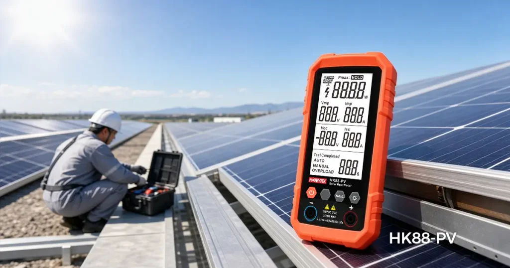
A Solar Panel Tester MPPT Meter is a photovoltaic testing instrument that adjusts the electrical load on a panel to find the operating point where voltage multiplied by current is highest.
MPPT stands for maximum power point tracking. A compatible solar panel power tester helps evaluate the power available from a module at the time of measurement.
The main parameters used in this assessment are:
- Pmax: Maximum power.
- Vmp: Voltage at maximum power.
- Imp: Current at maximum power.
- Voc: Open-circuit voltage.
- Isc: Short-circuit current.
These readings describe different operating conditions. Although an instrument may present them together, Voc, Isc and maximum power cannot be measured at the same electrical operating point.
An MPPT solar tester is useful for field checks, module comparisons and initial troubleshooting. A handheld power reading does not, by itself, certify a module’s nameplate rating or predict its daily energy production.
Why Measuring Voc and Isc Is Not Enough
Voc and Isc are useful starting points, but neither measures useful power delivered to a load.
At open circuit, current is zero. During a short-circuit test, terminal voltage is approximately zero. In both cases, output power at the measurement point is approximately zero because:
Power = Voltage × Current
Consequently, multiplying Voc by Isc does not give the panel’s maximum power.
For example, suppose a panel has these illustrative readings:
| Parameter | Reading |
|---|---|
| Voc | 49 V |
| Isc | 11 A |
| Vmp | 41 V |
| Imp | 10 A |
Its measured maximum power is:
Pmax = 41 V × 10 A = 410 W
Multiplying 49 V by 11 A gives 539 W, but those two values occur under different conditions and are not an available operating point.
Fluke explains that some defects reduce maximum power without being identified by Voc and Isc testing alone. Testing performance under load therefore provides additional diagnostic value. Source: Fluke’s explanation of Voc and Isc testing limitations.
How MPPT Testing Measures Real Panel Performance
A panel’s voltage and current change as its electrical load changes. An MPPT tester searches for the combination that produces the highest measured power.
This answers a practical question:
How much power can this panel provide under the sunlight and temperature conditions present now?
For meaningful comparisons, test panels under similar conditions and record irradiance and module temperature where possible. Moving clouds, changing panel angles and temperature differences can otherwise obscure the result.
A handheld MPPT reading also differs from a complete I-V curve. If a persistent problem needs deeper investigation, an I-V curve tracer can reveal how current changes across the voltage range. Laboratory module measurements use controlled conditions and uncertainty management to establish accurate power results. Source: NLR module measurement methods.
Understanding Pmax, Vmp, Imp, Voc and Isc
| Parameter | Meaning | Practical use |
|---|---|---|
| Pmax, W | Highest measured power under the test conditions | Comparing available module output |
| Vmp, V | Voltage at the maximum power point | Checking operating voltage under load |
| Imp, A | Current at the maximum power point | Checking current delivered at peak power |
| Voc, V | Voltage with no external load | Checking voltage and equipment compatibility |
| Isc, A | Current during a controlled short-circuit measurement | Assessing current capability under the test conditions |
The most useful relationship is:
Pmax = Vmp × Imp
For a Voc Isc Vmp Imp tester, assess both the available functions and their specified accuracy. Display resolution—the smallest number shown—is not the same as measurement accuracy.
Step-by-Step Guide to Testing a Solar Panel
1. Check the panel and tester specifications
Read the panel label and record Pmax, Vmp, Imp, Voc and Isc.
Confirm that the module’s expected voltage, current and power all fit within the tester’s permitted input limits. Consider cold-weather increases in Voc and any manufacturer-required allowances.
A compatible power rating alone is insufficient: a panel can remain below the wattage limit while exceeding the current limit.
2. Prepare a safe test setup
Inspect the panel, leads and connectors for damage, contamination or moisture.
If the panel is installed, follow the system manufacturer’s shutdown and isolation procedure before separating it from other equipment. An illuminated PV module can remain electrically energized after the inverter is switched off. Installed-system work should be performed by a qualified person.
Use the tester only in the connection arrangement permitted by its manual.
3. Choose stable sunlight
Position the panel in unobstructed sunlight with a consistent orientation.
Avoid shadows from your body, cables, trees or nearby structures. Record the time, weather, panel orientation and, where available, irradiance in the panel’s plane and module temperature.
4. Connect using the documented procedure
Confirm polarity and use correctly rated, manufacturer-approved mating connectors and test leads.
Follow the meter’s connection sequence. Do not improvise a short-circuit current test with loose wires or an unsuitable multimeter.
5. Run the test and record the readings
Select the appropriate mode according to the operating manual.
Record Pmax, Vmp, Imp, Voc and Isc where supported. Repeat the test under stable conditions to determine whether the result is consistent, observing the instrument’s measurement-duration and cooling requirements.
6. Compare results in context
Compare identical modules tested close together in time, at similar temperatures and orientations.
If a panel gives a persistently lower result, investigate environmental and connection factors before concluding that the module is defective.
7. Finish safely
End the measurement and follow the documented procedure to establish a no-load condition before separating PV connectors. Switching off a display is not proof that current has stopped.
Why Test Results May Differ from the Rated Power
A panel’s nameplate power is normally specified at Standard Test Conditions, or STC:
- Irradiance of 1,000 W/m².
- Cell temperature of 25°C.
- Reference solar spectrum of AM1.5.
These are reference conditions, not a promise of constant outdoor output. Source: NREL photovoltaic test-condition definitions.
Outdoor sunlight is often below the reference irradiance, while cells frequently operate above 25°C. Both affect output; orientation, shading, dirt and aging also matter. Source: NREL’s Understanding Solar Photovoltaic System Performance.
For example, a 400 W panel producing 320 W during a field test is delivering 80% of its nameplate power at that moment. That does not establish a 20% defect or degradation loss.
A reliable assessment needs the test conditions, appropriate correction methods and measurement uncertainty. There is no universal pass/fail percentage for an uncorrected outdoor power reading.
Safety Tips for Connecting MC4 Solar Panels
PV connectors require careful handling because DC circuits can sustain an arc when opened under load.
Stäubli explicitly states that PV connectors must not be disconnected under load and that unmated connectors must be protected from dirt and moisture. Source: Stäubli MC4-Evo 2 assembly instructions.
During testing:
- Confirm a no-load condition before connecting or disconnecting.
- Use connector combinations approved by their manufacturers; similar appearance does not establish compatibility.
- Keep connectors clean and dry, and inspect leads before use.
- Keep voltage, current and power within every applicable equipment limit.
- Follow the prescribed protective-equipment and isolation procedures.
For the HK88PV, the supplied specification lists CAT III 150 V. This marking does not permit inputs above 150 V or override other input restrictions. Likewise, an OL indication is not permission to deliberately connect an out-of-range source.
How to Identify Underperforming or Faulty PV Modules
A solar panel diagnostic tool helps identify patterns that deserve further investigation. It does not establish the cause of every abnormal reading.
| Observed pattern | Possible explanations | Useful next step |
|---|---|---|
| Normal-looking Voc but low Pmax | Shading, connection resistance or a module problem under load | Remove environmental causes and repeat the test |
| Lower current than comparable panels | Lower irradiance, dirt, shading or module damage | Compare under matched conditions |
| Lower operating voltage | Higher temperature, bypass-diode activation or a module fault | Compare temperatures and seek further testing if persistent |
| Rapidly changing power | Moving clouds, intermittent shading or an unstable connection | Retest in stable sunlight and inspect connections safely |
| Consistently low output from one identical module | Possible module-specific degradation or damage | Confirm with professional diagnostic testing |
Record the module identity, readings and test conditions. A repeated difference under comparable conditions is more informative than a single low number.
Persistent abnormalities may justify I-V curve tracing, thermal inspection or other specialist tests.
Is the Honeytek HK88PV a Suitable Solar Panel Power Tester?
The Honeytek HK88PV 2000W Solar Panel Tester MPPT Meter is worth considering for users who need field power measurements alongside basic PV electrical checks, provided the intended module fits its confirmed operating limits.
The supplied specifications list the following:
| Function | Range | Resolution | Stated accuracy |
|---|---|---|---|
| Open-circuit voltage | 12–99.9 V | 0.1 V | ±(1.5% + 5 digits) |
| Open-circuit voltage | 100–150 V | 1 V | ±(1.0% + 5 digits) |
| Power | 5–10 W | 0.1 W | ±(1.0% + 5 digits) |
| Power | 11–500 W | 0.1 W | ±(1.0% + 10 digits) |
| Power | 501–999.9 W | 0.1 W | ±(1.5% + 5 digits) |
| Power | 1000–2200 W | 1 W | ±(1.0% + 5 digits) |
| Short-circuit current | 0–20 A | 0.1 A | ±(1.5% + 5 digits) |
Ranges and accuracy bands are reproduced from the supplied data. The percentage-plus-digits convention should be confirmed in the operating manual; the accuracy-band boundaries are retained as provided.
Practical features include:
- Backlit LCD for display visibility.
- MAX function for viewing a captured maximum.
- Data Hold for recording a reading.
- Automatic power-off.
- SMART/AUTO selection.
- Two 1.5 V batteries.
- Overrange indication and measurement-entry restriction, as described in the specification.
The supplied documentation states that accuracy is determined under standard light sources. Field measurements also depend on changing sunlight, temperature and the test setup.
Two details should be confirmed before purchase or use. The product name says “2000W,” while the table lists a measurement range extending to 2200 W; a displayed measurement range does not independently establish a safe continuous operating rating. Also, the supplied table does not give separate Vmp and Imp accuracy specifications or confirm the exact five-parameter display sequence.
For suitable modules, the HK88PV offers a practical way to add power measurement to voltage and current checks. Contact Honeytek with your panel’s Voc, Isc and Pmax to confirm compatibility and obtain the current operating manual.
Frequently Asked Questions
Can a multimeter measure solar panel power?
A suitable multimeter can measure electrical parameters, but a voltage-only reading does not establish maximum power. Measuring Pmax requires voltage and current at the same loaded operating point and a method of finding that point.
Does an MPPT tester measure daily energy production?
A power reading is measured in watts. Daily energy is measured in watt-hours or kilowatt-hours and requires measurement or estimation over time.
Does low measured power mean the panel is faulty?
No. First check sunlight, temperature, orientation, shading, cleanliness and connections. Repeat the measurement under comparable conditions before diagnosing a fault.
Can the HK88PV test a complete solar string?
Do not assume it can. Series connections increase voltage, and parallel connections increase current. Use it only for configurations explicitly permitted by Honeytek’s current manual and within all confirmed input limits.
What makes a solar panel test more accurate?
Use a suitable instrument with known calibration status, stable sunlight, sound connections and repeatable positioning. Record irradiance and module temperature when comparing field results with nameplate performance.
