
A voltage detector — also called a VD (Voltage Detector), reset IC, or supervisor IC — is an integrated circuit designed to monitor voltage levels in power lines. When the voltage rises above or falls below a preset threshold, it outputs a detection signal.
These devices are crucial in ensuring the safe and reliable operation of electrical systems by signaling abnormal voltage conditions, triggering resets, or controlling power sequences.
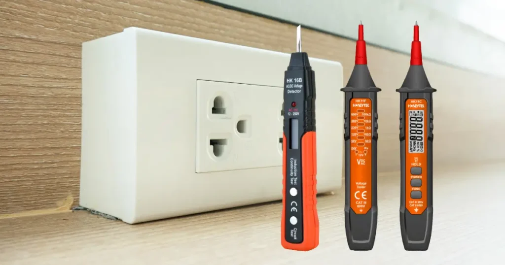
What is a Voltage Detector?
In its simplest form, a voltage detector measures an input voltage and produces a corresponding output.
The basic input-output relationship is:
| Monitored Voltage | Output |
|---|---|
| Above release voltage (detection voltage + hysteresis) | “H” (High) |
| Below detection voltage | “L” (Low) |
Note: In products with “Active L” output, the signal is “L” during detection.
Key Applications of Voltage Detectors
1. Battery and Power Supply Monitoring
Voltage detectors monitor supply lines for voltage anomalies. If voltage is abnormal, they signal downstream components to take action — such as shutting down the system.
They are also used to monitor battery voltage. When voltage drops, the detector can indicate low power status or initiate system shutdown to protect components.

2. MCU Reset / Power-On Reset (POR)
Microcontrollers (MCUs) require a specific operating voltage range.
A voltage detector monitors the MCU’s power line, outputting a reset signal if voltage falls below the operational threshold — stopping the MCU to prevent malfunction.
On startup, it ensures voltage is stable before the MCU begins execution, preventing erratic behavior.

3. Power Sequence Control
Some MCUs and modules require multiple power rails (e.g., core voltage, main supply) to turn on and off in a specific order.
Voltage detectors monitor each rail and trigger the next power stage only when conditions are met, simplifying power sequencing design.

How Does a Voltage Detector Work?
Voltage detectors use internal comparator circuits, reference voltages, and transistor-based output drivers to determine when voltage crosses set thresholds.
Let’s examine the four main operating states using an L output, N-channel open-drain output example where monitored voltage equals input voltage.
A) Release State (Detection Voltage < Input Voltage)
- When input voltage is higher than the set detection voltage, the comparator and inverter turn the output driver FET OFF (Hi-Z).
- The RESETB pin outputs High through pull-up voltage.
- Detection voltage is determined by resistors R1, R2, and R3: Detection Voltage=VREF × (R1+R2+R3) / (R2+R3)
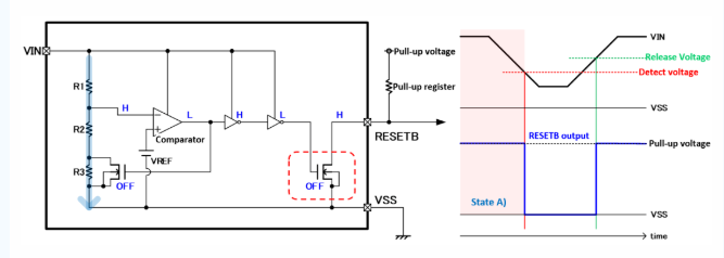
B) Release → Detection State Transition
- As voltage drops to or below the detection voltage, the comparator logic inverts.
- The output driver FET switches ON, pulling RESETB to Low (0V).
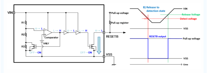
C) Detection State (Input Voltage < Detection Voltage)
- In detection mode, a shorting FET bypasses resistor R3.
- Release voltage is determined by R1 and R2: Release Voltage=VREF × (R1+R2) / R2
- The difference between detection and release voltage is called hysteresis width, preventing frequent switching due to small voltage fluctuations.

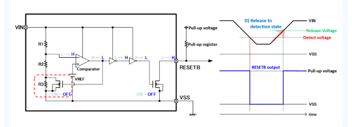
D) Detection → Release State Transition
- When voltage rises above the release voltage, the comparator logic reverts, turning the output driver FET OFF.
- RESETB returns High, signaling a normal state.
How to Use a Voltage Detector Safely
- Verify Specifications: Choose a model rated for your voltage range and application (e.g., CAT II, CAT III safety ratings).
- Understand Output Type: Active-H vs. Active-L outputs behave differently in control circuits.
- Consider Hysteresis: A small hysteresis range can cause false triggering in noisy environments.
- Follow Power-Up Sequence: For MCUs, ensure stable supply voltage before releasing reset.
- Test Before Deployment: Verify response time, detection accuracy, and reset behavior in your system.
Conclusion
Voltage detectors are small but essential components in electronics, ensuring safe startup, proper sequencing, and immediate fault detection. Whether used in battery-powered devices, industrial control systems, or complex embedded boards, they protect equipment and enhance reliability.
By understanding their definition, usage, and working principle, engineers and technicians can select the right voltage detector for their needs and integrate it effectively into their designs.
