
Introduction: A New Way to Diagnose Electronic Faults
In the world of electronics repair, precision and speed matter. Whether you are troubleshooting a faulty circuit board, identifying overheating components, or ensuring the stability of a system under load, finding the root cause quickly can save hours of work.
Infrared thermal imaging cameras have become indispensable tools for electronic enthusiasts, repair technicians, and engineers. By visualizing heat distribution in real time, thermal imagers allow you to see what’s invisible to the naked eye — temperature differences that reveal hidden electrical faults.
Brands like Honeytek, a professional electronic measurement tool manufacturer, have made this technology more accessible than ever, offering compact and affordable thermal imagers for engineers, labs, and field technicians.
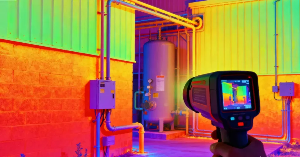
Why Use an Infrared Thermal Imaging Camera in Electronic Repair?
Traditional troubleshooting often relies on trial and error — measuring voltages, testing continuity, or physically inspecting every component. Thermal imaging transforms this process by instantly showing where the problem lies.
1. Non-Contact, Real-Time Diagnostics
Thermal cameras detect infrared radiation emitted by components, converting it into visible color maps. This allows technicians to identify faults without touching the circuit, minimizing the risk of damage or electric shock.
2. Instant Visualization of Hotspots
Instead of checking each component manually, a quick scan reveals hot or cold spots across the circuit board, helping pinpoint the faulty resistor, capacitor, or IC in seconds.
3. Efficient and Safe Testing
Thermal inspection can be performed without powering down the circuit, which is particularly useful for diagnosing intermittent faults or real-time load issues.
4. Ideal for R&D, Quality Control, and Maintenance
From design verification to after-sales repair, infrared thermal imaging supports every stage of the product life cycle. It ensures component reliability, detects design flaws, and verifies proper heat dissipation in electronic assemblies.
Key Applications in Electronic Diagnostics
1. Circuit Board (PCB) Fault Detection
One of the most common uses of thermal imaging cameras in electronics is PCB diagnosis.
When a printed circuit board is powered on, defective components — such as resistors, capacitors, or IC chips — often generate abnormal heat. With a thermal imager, these components appear as bright hotspots on the thermal image, making them easy to locate.
This approach eliminates the need for circuit diagrams or disassembly, allowing fast, non-destructive fault localization.
Example Use Case:
A technician notices a smartphone that won’t power on. Instead of probing each voltage line manually, a quick thermal scan shows one area of the motherboard heating abnormally — revealing a shorted capacitor in seconds.
2. Overheating Analysis in Electronic Devices
Thermal imaging is also invaluable for detecting overheating issues in electronics like computers, power supplies, or chargers.
Components such as CPUs, MOSFETs, and voltage regulators can show abnormal temperature rises before failure. Monitoring these with a thermal camera helps engineers optimize cooling systems and circuit layouts, preventing long-term damage.
Example Use Case:
During laptop testing, a Honeytek TP175 mobile thermal camera reveals a hotspot near the power IC. Engineers adjust the heat sink design, improving stability and extending the product’s lifespan.
Step-by-Step Guide: Using a Thermal Imaging Camera for Electronic Repair

To make the most of your thermal imager, follow this simple process:
Step 1: Calibration and Preparation
Before scanning, calibrate the camera to ensure accurate temperature readings. Adjust emissivity values if needed — most circuit boards have an emissivity around 0.95.
Step 2: Power the Device and Observe
Turn on the device under normal operating conditions. Slowly scan the PCB or component area. A real-time thermal image will appear, displaying temperature gradients across the surface.
Step 3: Identify Abnormal Heat Patterns
Look for hotspots or unusually cold spots. A single component significantly hotter than its surroundings often indicates a short circuit, leakage, or overload.
Step 4: Pinpoint and Verify the Fault
Once you locate the suspicious component, verify it using traditional tools like a multimeter for confirmation.
Step 5: Repair and Re-Test
Replace or repair the faulty part, then re-scan the board to ensure the temperature has normalized.
Advantages of Using Thermal Imaging in Electronics
| Advantage | Description |
|---|---|
| Speed | Instantly identify faults without lengthy probing or disassembly. |
| Safety | No need to touch live circuits or high-voltage areas. |
| Accuracy | Clearly visualize abnormal temperature differences. |
| Non-Destructive | Diagnose problems without physically altering the board. |
| Versatility | Suitable for design, testing, maintenance, and repair. |
Recommended Thermal Imaging Cameras for Electronics
When selecting a thermal imaging camera for electronic repair, consider factors like resolution, temperature range, and portability.
1. Honeytek TP170 / TP175
Compact plug-in thermal imaging cameras designed for engineers and hobbyists.
- Resolution: 160×120 / 256×192
- Features: Plug-and-play via USB or smartphone; real-time thermal video; high accuracy
- Best For: PCB diagnostics, overheat analysis, R&D testing
These models balance affordability with professional-grade performance, making Honeytek a top choice for technicians who value clarity, portability, and precision.
2. FLIR One Pro
A premium model offering high dynamic range and advanced image blending. Excellent for professional R&D labs but more expensive.
3. Infiray P2 Pro
Lightweight with sharp imaging quality, suitable for mid-range users seeking better detail and app control.
Tips for Better Thermal Inspection Results
- Allow the device to warm up for a few seconds before capturing images.
- Avoid reflective surfaces that can distort readings.
- Use macro lenses or close-focus adapters for small PCB components.
- Keep consistent distance from the target to ensure uniform focus.
- Compare images over time to monitor thermal behavior under different loads.
Frequently Asked Questions (FAQ)
Q1: Can I use a thermal imaging camera to find short circuits?
Yes. Short circuits cause excessive current flow, generating localized heat. A thermal imager quickly highlights the hotspot area, allowing you to identify the defective component instantly.
Q2: Do I need to turn off power before using a thermal camera?
No. One of the main advantages of infrared thermal cameras is that they allow live, non-contact testing, meaning you can safely detect heat patterns while the circuit is powered on.
Q3: Are smartphone thermal cameras accurate enough for electronics repair?
Absolutely. Devices like the Honeytek TP175 provide sufficient resolution and temperature sensitivity for most PCB diagnostics and equipment heat analysis tasks.
Q4: What temperature range should I look for?
For electronic applications, a range of -20°C to 250°C is usually sufficient. This covers most PCB and component operating temperatures.
Q5: Can thermal imaging replace traditional testing tools?
No, but it complements them perfectly. A thermal camera helps you find the problem fast, while tools like multimeters confirm the electrical condition.
Conclusion: The Future of Smart Electronic Diagnostics
Infrared thermal imaging cameras have transformed how we approach electronic repair. They offer real-time, non-contact, and highly visual diagnostics, saving hours of manual testing and improving repair accuracy.
From hobbyists to professional engineers, anyone working with electronics can benefit from this powerful tool. Whether identifying a faulty chip, optimizing heat dissipation, or preventing component burnout, thermal imaging provides unmatched insight into electronic systems.
