
A digital multimeter can show voltage on a disconnected conductor, even when that wire is not connected to an energized source. And when you measure a variable frequency drive (VFD), the display may fluctuate or show readings that are difficult to interpret.
These situations have different causes. LoZ (low impedance) mode can help check for capacitively coupled ghost voltage. VFD mode, sometimes implemented with a low-pass filter (LPF), can help make drive-output measurements more useful. Neither mode replaces safe isolation procedures or the instrument’s instructions.
Part 1: What Is Ghost Voltage, and How Does LoZ Help?
Ghost voltage—also called phantom or induced voltage—can appear when an energized conductor runs alongside a disconnected wire. The conductors can couple capacitively, allowing a small current to induce a voltage on the disconnected wire.
A high-impedance digital meter draws very little current, so it may display this coupled voltage. The reading can be confusing: it may look like the wire is energized even though it is not connected to a low-impedance power source.
A meter’s LoZ mode places a lower input impedance across the measurement. This can reduce a voltage caused by weak capacitive coupling, often making the reading drop substantially. If the voltage remains, it may be supplied by a stronger source and should be investigated.
A low or zero LoZ reading does not prove a circuit is safe to touch. Follow lockout/tagout procedures and verify absence of voltage using the approved test method for your workplace. LoZ can load a circuit and may affect sensitive electronics; use it only on circuits and equipment for which the meter manufacturer permits it.
Part 2: Measuring VFD Outputs
VFDs control motor speed by switching their output rapidly. The motor voltage waveform can contain high-frequency switching components as well as the fundamental frequency that determines motor speed. A meter not designed for this signal may show unstable or misleading voltage or frequency readings.
A meter’s VFD mode may use filtering, specialized processing, or both to reduce the influence of switching components. On meters that implement a low-pass filter, the LPF helps emphasize the lower-frequency component of the waveform. The exact behavior and suitable measurement range depend on the meter.
VFD mode does not make every drive-output measurement equivalent to a dedicated power analyzer or oscilloscope reading. Consult the drive and meter manuals, especially when interpreting output voltage, frequency, or PWM waveforms.
A Practical Diagnostic Workflow
Scenario A: Checking a suspected ghost voltage
- Identify the conductors and circuit, then follow your site’s isolation and verification procedure.
- Select the meter’s LoZ voltage mode, following the instrument manual.
- Measure between the conductor and the appropriate reference point using correctly rated leads and PPE.
- Compare the LoZ result with the standard high-impedance voltage reading if your procedure calls for it.
- Treat any persistent voltage as potentially hazardous until its source is identified and the circuit is proven safe using approved procedures.
Scenario B: Checking a VFD and motor
- Review the VFD and meter manuals for approved measurement points, modes, and ratings.
- Select the meter’s VFD mode for the measurement if recommended by the manufacturer.
- Measure at the specified input or output terminals using correctly rated accessories and safe working practices.
- Record the reading along with drive settings, motor speed or operating frequency, and load conditions.
- Compare results with the drive and motor documentation. If readings remain inconsistent, use the manufacturer’s diagnostic procedure or an instrument designed for detailed drive waveform analysis.
Why the Right Meter Matters
When working around electrical distribution panels and drives, select a meter and accessories rated for the installation’s voltage and measurement category. Check the instrument markings and manual for the exact limits and permitted uses; a CAT rating alone does not guarantee that every measurement method is appropriate for every circuit.
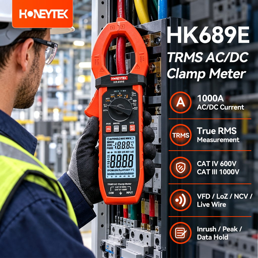
The Honeytek HK689E AC/DC clamp meter includes LoZ AC/DC voltage measurement, VFD mode, True RMS measurement, and a backlit EBTN display. Its stated safety category is CAT III 1000 V / CAT IV 600 V. Confirm the manual and ratings for your specific measurement before use.
Conclusion
LoZ mode can help distinguish weak capacitively coupled voltage from voltage supplied by a stronger source. VFD mode can make certain drive-output readings easier to interpret by reducing the influence of switching components. Use each function within the meter’s stated limits, and follow established electrical safety procedures throughout diagnosis.
For specifications and measurement functions, visit the Honeytek HK689E product page.
