
When a motor runs hotter than usual or a transformer begins drawing abnormal current, a basic continuity check may not reveal the cause. The winding can still appear continuous even when it has a poor connection, an electrical imbalance, or a change in its magnetic characteristics.
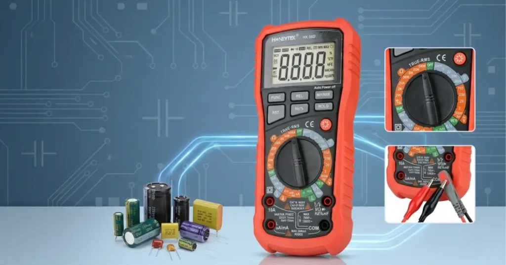
The Honeytek HK56D combines inductance, resistance, capacitance, frequency, temperature, and True RMS measurements in one portable instrument. This makes it useful for comparative testing of motor phases, transformer windings, contactors, relays, solenoids, and other coil-based components.
This article explains where the HK56D fits into a practical troubleshooting process—and where a different test instrument is still required.
Why Continuity Alone Is Not Enough
A winding is made from a long length of copper conductor, so a healthy high-power coil can have very low DC resistance. That often creates confusion: a continuity buzzer may sound even when the component is not short-circuited.
This is also a recurring question among repair technicians. In one Reddit discussion, users pointed out that a high-power choke may look almost like a short on a standard multimeter because its winding contains only a few turns of low-resistance copper. Measuring inductance provides more useful information about whether the coil is behaving as expected.
For motors and transformers, technicians should therefore look beyond a simple beep and ask:
- Are equivalent windings electrically balanced?
- Does one phase have a noticeably different inductance?
- Is a terminal connection adding resistance?
- Do readings remain stable when the test is repeated?
- Has the result changed from the equipment’s historical baseline?
The most useful answer normally comes from comparing several measurements—not from treating one value as a complete diagnosis.
What the Honeytek HK56D Measures

The HK56D is a handheld digital multimeter with dedicated inductance ranges and supporting electrical functions.
| Measurement | HK56D capability |
|---|---|
| Inductance | 2 mH, 20 mH, 200 mH, 2 H and 20 H ranges |
| Resistance | Up to 200 MΩ |
| Capacitance | Up to 10 F, depending on range |
| Frequency | Up to 10 MHz |
| Temperature | −20°C to 1,000°C |
| AC measurement | True RMS |
| Direct current | Up to 20 A, subject to input-time limits |
| Additional functions | Continuity, diode, NCV, MAX/MIN and Data Hold |
| Range selection | Manual |
| Display | 1,999 counts |
| Safety category | CAT III 1000 V |
These published specifications are listed in the current Honeytek product catalogue. Users should confirm the applicable accuracy, fuse protection, environmental limits, and maximum input duration in the latest product manual before testing.
A More Reliable Way to Check a Three-Phase Motor
The aim of an initial HK56D check is not to prove that a motor is fault-free. It is to identify abnormal differences that justify closer investigation.
1. Document the operating problem
Before disconnecting anything, record the symptoms and nameplate information:
- Rated voltage, current, power, and frequency
- Star or delta connection
- Overheating or overload history
- Abnormal noise or vibration
- Starting difficulty
- Drive fault codes
- Previous resistance, temperature, or inductance readings
A test value has much more meaning when it can be compared with an earlier measurement or an identical serviceable motor.
2. Isolate the motor completely
Apply the approved lockout/tagout procedure and verify that the circuit is de-energized.
Where permitted by the equipment manufacturer, disconnect the motor from the VFD, soft starter, contactor, surge suppressor, and other external circuits. Connected electronics and parallel paths can distort the reading. They may also retain dangerous stored energy after the main supply has been disconnected.
3. Compare phase-to-phase resistance
For an accessible three-phase motor, measure the same three terminal combinations:
- U–V
- V–W
- W–U
Use the same leads, probe pressure, terminal locations, and meter range for every reading. Watch for an open circuit, an unstable value, or one measurement that differs substantially from the others.
However, keep the instrument’s resolution in mind. Large motors may have winding resistance in the milliohm region. Maintenance professionals discussing this issue on Reddit frequently note that an ordinary handheld resistance range may not resolve small differences in large machines; a dedicated four-wire micro-ohmmeter is more appropriate when precise low-resistance results are required.
4. Compare phase-to-phase inductance
Switch to the appropriate inductance range and repeat the U–V, V–W, and W–U measurements.
For repeatable results:
- Keep the test leads in the same physical arrangement.
- Use clean, secure terminal contact.
- Allow each reading to stabilize.
- Test all phases at a similar winding temperature.
- Keep the rotor in the same position.
- Repeat any unexpected measurement before drawing a conclusion.
A significant inductance difference can indicate a change in the effective turns, magnetic path, winding connection, or test setup. It is an investigation trigger—not an automatic pass/fail verdict.
5. Control the rotor position
Technicians often ask why a motor’s inductance changes when the shaft turns. The rotor alters the magnetic relationship inside the machine, so its position can affect the reading.
If the shaft moves during testing, a healthy phase may appear different simply because it was measured under a different magnetic condition. Keep the rotor stationary while comparing phases. If necessary, record all three readings at several clearly marked rotor positions and compare each set under identical conditions.
6. Record the measurement conditions
A useful service record includes more than three numbers:
| Record item | Example |
|---|---|
| Motor and asset ID | Pump Motor M-04 |
| Connection tested | U–V, V–W, W–U |
| Rotor position | Shaft mark at 12 o’clock |
| Winding temperature | 24°C |
| Meter and range | HK56D, 200 mH |
| External circuits | VFD disconnected |
| Resistance readings | Recorded for all three combinations |
| Inductance readings | Recorded for all three combinations |
| Inspection notes | Terminal condition, odor, discoloration |
Trend data collected under consistent conditions is generally more valuable than an isolated reading taken after a failure.
How to Check Transformer Windings
Transformer windings should be evaluated by function and connection—not simply compared indiscriminately. A primary winding and secondary winding normally have different turns, conductor sizes, resistance, and inductance.
Identify comparable windings
Use the transformer schematic or nameplate to identify:
- Primary and secondary windings
- Corresponding phases
- Center taps
- Voltage-selection taps
- Auxiliary windings
- Thermal protection devices
Only compare equivalent phases, matching taps, or results from an identical transformer with the same configuration.
Check continuity and resistance
An open reading may indicate a broken winding, operated thermal fuse, disconnected tap, or poor terminal connection. An unexpectedly high or unstable value may point to corrosion, damaged joints, or poor probe contact.
A transformer winding can legitimately have low DC resistance, so continuity by itself does not establish winding condition. A Reddit engineering discussion on this subject recommends checking inductance when continuity gives too little information about the winding’s behavior.
Measure and compare inductance
Disconnect external loads and measure equivalent windings under the same conditions. Record the exact tap positions and terminal combinations.
Inductance depends on the number of effective turns, core material, magnetic path, air gap, connected windings, and the instrument’s test conditions. For that reason, results from two different meters may not agree exactly. Comparing readings taken with the same HK56D, leads, setup, and reference component produces more useful maintenance data.
What Different Results May Mean
| Observation | Possible causes to investigate |
|---|---|
| Open resistance and no stable inductance | Broken conductor, open winding, operated thermal device, or poor connection |
| One motor phase has higher resistance | Loose terminal, corrosion, damaged joint, or winding damage |
| One equivalent phase has lower inductance | Shorted turns, connection error, rotor-position effect, or winding difference |
| Inductance changes between repeated tests | Moving rotor, inconsistent contact, connected circuitry, or electrical interference |
| All static readings are balanced but the motor overheats | Supply imbalance, excessive load, cooling failure, bearing problem, VFD issue, or insulation deterioration |
| Transformer readings differ between taps | Different effective turns or an incorrect comparison |
| Results differ between meters | Different test methods, frequencies, lead effects, resolution, or equivalent-circuit assumptions |
Treat this table as a troubleshooting guide rather than a set of universal failure limits. Final acceptance criteria should come from the equipment manufacturer, an applicable maintenance standard, or a validated baseline.
Can the HK56D Detect Shorted Turns?
It can help identify a developed fault that produces a measurable difference between equivalent windings. A turn-to-turn short may reduce the effective turns or alter the coil’s magnetic behavior, creating an inductance imbalance.
However, an early insulation weakness may not appear during a low-energy handheld inductance test. Reddit discussions among motor and electronics technicians regularly recommend comparing inductance or coil quality between equivalent windings, while also recognizing that more specialized testing may be needed to confirm a turn fault.
When a shorted turn is suspected, consider follow-up testing with:
- A surge comparison tester
- A dedicated winding analyzer
- A four-wire winding-resistance instrument
- An insulation-resistance tester
- Thermal imaging under controlled operating conditions
- Current and vibration analysis
An LCR Check Is Not an Insulation Test
This distinction is essential.
The HK56D measures ordinary resistance up to 200 MΩ, but it does not replace an insulation-resistance tester that applies a specified DC test voltage between windings, phases, and ground.
A motor can show balanced phase resistance and inductance while still having deteriorated insulation to ground. Conversely, a high insulation-resistance value does not prove that every turn within a winding is healthy.
Fluke’s motor-testing guidance similarly emphasizes that no single good result proves the entire motor is sound; winding balance, phase-to-ground insulation, the supply circuit, and other mechanical and electrical conditions must be considered together.
Use the right instrument for the diagnostic question:
- HK56D inductance and resistance: Comparative winding and component checks
- Insulation-resistance tester: Insulation between conductors, windings, and ground
- Four-wire micro-ohmmeter: Precise low winding and connection resistance
- Surge tester: Turn-to-turn, coil-to-coil, and phase-to-phase weaknesses
- Clamp meter: Phase-current and load comparisons
- Thermal camera: Operating hot spots and unequal heating
- Vibration analyzer: Bearings, alignment, looseness, and rotor condition
Common Field Questions
Why does a coil look shorted on the resistance range?
Copper windings can have very low DC resistance by design. Check the expected specification and compare inductance with an equivalent coil before concluding that it is shorted.
Can a motor be tested while connected to a VFD?
For resistance or inductance testing, isolate the motor in accordance with the motor and drive manufacturers’ procedures. The VFD can affect the measurement and may contain stored voltage.
Should all three motor phases read exactly the same?
Not necessarily. Manufacturing tolerance, temperature, rotor position, terminal configuration, and meter resolution can introduce differences. Look for repeatable imbalance and compare the results with manufacturer limits or baseline data.
Why are my readings unstable?
Common causes include oxidized terminals, inconsistent probe pressure, shaft movement, long or moving leads, connected components, and readings near the meter’s resolution limit.
Can one HK56D reading confirm that a transformer is healthy?
No. It is most effective as a comparative screening tool. Transformer condition may also require insulation resistance, turns-ratio, excitation-current, winding-resistance, dielectric, or other specialized tests.
Build Better Maintenance Decisions with Comparative Data
The Honeytek HK56D gives technicians a practical way to add inductance measurements to routine motor and transformer troubleshooting without carrying a separate basic inductance meter.
Its greatest value is not a single isolated number. It is the ability to:
- Compare equivalent motor phases
- Check corresponding transformer windings and taps
- Investigate open or inconsistent coils
- Screen relays, contactors, solenoids, and chokes
- Combine inductance with resistance, temperature, frequency, and True RMS measurements
- Create repeatable baseline and trend records
Used with consistent test conditions—and alongside the appropriate insulation, surge, thermal, current, and mechanical tests—the HK56D can help maintenance teams identify abnormalities earlier and make better-informed decisions about inspection, repair, or replacement.
Related Products & Resources
- HK68C 5,999 Counts PC-Link Digital Multimeter — product page, datasheet, and USB driver download
- HK56D 1,999 Counts Inductance Digital Multimeter — product page, inductance accuracy chart
- All HONEYTEK Digital Multimeters
- Contact HONEYTEK for OEM/ODM
