
Selecting a two-pole voltage tester is not simply a matter of comparing voltage ranges, displays or purchase prices. For electricians, maintenance teams and electrical distributors, the more important questions are:
- Has the tester been evaluated against the applicable safety standard?
- Is its measurement category appropriate for the installation?
- Can the stated certification be independently verified?
- Will the tester continue to indicate voltage if its batteries are depleted?
- Is it suitable for proving dead, testing an RCD or working on a photovoltaic system?
These concerns are frequently raised by working electricians. In Reddit discussions, professionals repeatedly emphasize three practical points: use an adequately rated contact tester, verify the tester before and after proving dead, and never treat a non-contact voltage detector as a substitute for an approved two-pole instrument.
This guide explains the roles of CE marking, the GS mark and VDE certification, the relevance of EN/IEC 61243-3, and the factors buyers should examine when specifying a professional two-pole voltage tester.
It also compares the Honeytek HK235A and HK235B, two models intended for building electrical work, maintenance, RCD testing and, in the case of the HK235B, higher-voltage DC applications such as solar PV systems.
Safety notice: Electrical testing should only be performed by trained and authorized personnel using procedures required by the applicable national regulations and employer safety program. Certification does not make a tester suitable for every circuit or replace safe-isolation procedures.
Why Certification Matters for a Two-Pole Voltage Tester
A two-pole tester is often used at the most safety-critical moment of a job: determining whether conductors are energized before work begins.
If a tester gives a false indication, cannot withstand a transient overvoltage or is used outside its rated category, the consequences may include:
- Electric shock
- Arc flash
- Internal tester rupture
- Burns caused by an electric arc
- Damage to the installation
- Incorrect confirmation that a circuit is de-energized
- Failure to meet an employer’s safe-working procedure
- Rejection during a procurement or job-site safety audit
A printed voltage range alone does not establish that a tester can safely withstand the transient energy present at a distribution board or service entrance. Buyers should examine the complete combination of the applicable standard, measurement category, working-voltage rating, third-party certification and product documentation.
CE, GS and VDE: What Do the Marks Mean?
These markings are related, but they do not communicate the same information.
CE Marking
CE marking indicates that the manufacturer declares that a product complies with applicable EU harmonization legislation.
For electrical equipment within its scope, the current EU Low Voltage Directive is 2014/35/EU. The directive generally covers equipment designed for use between 50 and 1,000V AC or between 75 and 1,500V DC. The directive defines CE marking as the manufacturer’s indication that the equipment conforms to applicable EU requirements. EUR-Lex: Directive 2014/35/EU
CE marking is generally necessary for relevant products placed on the European Economic Area market, but it should not be presented as an independent product safety certificate. For many electrical products, the manufacturer is responsible for the conformity assessment and declaration.
A professional buyer should therefore request:
- The EU Declaration of Conformity
- The exact product model covered
- The applicable directives
- The standards used to demonstrate conformity
- The manufacturer or responsible economic operator
- Traceable technical documentation
A CE logo by itself is not enough to confirm third-party testing.
GS Mark: Geprüfte Sicherheit
GS stands for Geprüfte Sicherheit, meaning “tested safety.”
Unlike CE marking, the GS mark is a voluntary safety mark regulated under the German Product Safety Act. It requires assessment by an authorized GS body. According to Germany’s Federal Institute for Occupational Safety and Health, GS certification involves examination of a product prototype and checks of the manufacturing process.
GS-certified products are also subject to ongoing monitoring by an authorized certification body. However, the GS mark does not make claims about every aspect of product quality, performance or service life. Its focus is product safety when the product is used as intended or under reasonably foreseeable conditions. BAuA: Questions and Answers About the GS Mark
For procurement teams, a valid GS mark provides additional independent evidence beyond a manufacturer’s CE declaration.
VDE Certification
The VDE Testing and Certification Institute is an independent organization that evaluates electrical products against relevant VDE, EN and IEC standards and other applicable safety requirements.
VDE states that its certification process includes product examination, control of manufacturing facilities and regular production monitoring. Its online catalogue can also be used by buyers and market-surveillance authorities to check certified products. VDE: Marks and Certificates
The terms “VDE certified” and “tested by VDE” should not be used casually. Before purchasing or advertising a product as VDE certified, buyers and distributors should verify:
- The certificate number.
- The exact manufacturer name.
- The exact model designation.
- The standards shown on the certificate.
- The certificate’s current validity.
- Whether the mark printed on the product matches the authorized mark.
Honeytek documentation lists VDE, GS and CE for the HK235A and HK235B. A professional buyer should nevertheless request the current certificate and verify the model in the relevant certification database before placing a large order or publishing a certification claim.
EN/IEC 61243-3 and Two-Pole Voltage Detectors
IEC 61243-3 applies to two-pole low-voltage detectors used on electrical systems with nominal voltages up to 1,000V AC and 1,500V DC at frequencies below 500Hz.
An important distinction is that equipment covered by this standard is intended to indicate whether voltage is present. It is not necessarily intended to provide laboratory-grade measurement of an absolute voltage value. Measuring functions may be subject to additional requirements under standards such as IEC 61010-1 and IEC 61010-2-031. IEC: IEC 61243-3
The standard addresses safety-related characteristics such as:
- Reliable voltage indication
- Protection against electric shock
- Resistance to transient overvoltage
- Mechanical durability
- Probe and lead construction
- Environmental influences
- Clear indication of operating status
- Behavior during foreseeable use
- Dependable operation within the stated voltage range
Compliance should always be confirmed from the certificate and manufacturer documentation rather than inferred from appearance or marketing language.
The Topics Electricians Keep Discussing
Professional communities provide useful insight into how testers are used in practice. They are not substitutes for standards or regulatory guidance, but recurring discussions reveal the questions buyers should answer.
1. Should a Voltage Tester Be Proved Before and After Use?
Yes. A frequent recommendation among electricians is to check the tester on a proving unit or known live source immediately before and after testing the target circuit.
The sequence is often described as:
- Confirm the tester operates on a proving unit or known live source.
- Test the target conductors using the required combinations.
- Confirm the tester still operates on the proving unit or known live source.
This reduces the risk of relying on a tester that has failed during the test. Electricians discussing safe isolation on Reddit repeatedly recommend this “live-dead-live” procedure. Reddit discussion: voltage tester and proving-unit practice
A built-in self-test is useful, but it may not replace an external proving unit when the applicable safe-isolation procedure requires one.
2. Is a Non-Contact Voltage Tester Enough to Prove Dead?
No. A non-contact voltage tester can be valuable for preliminary screening and troubleshooting, but it can be affected by:
- Shielded conductors
- Cable construction
- Induced or phantom voltage
- Moisture
- Tester orientation
- Battery condition
- Electric-field strength
- DC circuits
Electricians regularly warn against cutting or touching conductors based only on a negative indication from a non-contact tester. A properly rated two-pole contact tester provides a direct test between two points and is the more appropriate tool for formal absence-of-voltage verification. Reddit discussion: limitations of non-contact voltage testers
3. Does Brand Matter More Than Certification?
Experienced electricians often recommend established brands, but the underlying concern is usually not the logo alone. It is whether the tester has:
- A suitable CAT rating
- Appropriate input protection
- Third-party certification
- Durable probes and leads
- Predictable indication behavior
- Accessible documentation
- A credible manufacturer and supply chain
A recognized brand does not eliminate the need to check the model-specific rating. Conversely, a lower-cost instrument should not be rejected solely on price if its certification, construction and documentation can be independently verified.
The recurring concern in professional discussions is that cost reductions must not come from inadequate input protection or unverified safety claims. Reddit discussion: tester input protection and third-party certification
4. Should Electricians Use a Two-Pole Tester or a Multimeter?
The correct choice depends on the task.
A two-pole voltage tester is optimized for quick, unambiguous voltage-presence testing. Many models can also perform continuity, polarity, phase-sequence and RCD tests.
A digital multimeter is better suited to diagnostic measurements requiring greater resolution, selectable functions or defined accuracy.
However, a multimeter introduces more opportunities for incorrect setup, including:
- Selecting the wrong function
- Leaving a lead in a current terminal
- Selecting an unsuitable range
- Misinterpreting a high-impedance phantom-voltage reading
For routine safe-isolation work, many electricians prefer a straightforward two-pole indicator and use a multimeter when detailed measurement is required.
Understanding CAT III and CAT IV Ratings
Measurement categories describe the transient environment in which test equipment is intended to operate. They are not simply quality grades.
CAT III
CAT III applies to measurements in a building’s fixed installation, including:
- Distribution boards
- Circuit breakers
- Busbars
- Fixed wiring
- Junction boxes
- Industrial feeders
- Permanently connected equipment
CAT IV
CAT IV applies closer to the origin of the low-voltage installation, where available transient energy may be higher. Examples include:
- Utility service entrances
- Electricity meters
- Primary overcurrent-protection equipment
- Outdoor conductors associated with the service
A rating such as CAT III 1000V / CAT IV 600V means the tester is rated for different working voltages in the two transient environments. It does not mean it can be used on every 1,000V or 1,200V circuit without considering the complete rating and manufacturer instructions.
For DC and photovoltaic work, verify both:
- The maximum DC working voltage
- The applicable measurement category at that voltage
Do not infer a DC category rating from an AC specification.
Honeytek HK235A and HK235B Comparison
The two Honeytek models share several safety and job-site features but cover different voltage ranges.
| Feature | HK235A | HK235B |
|---|---|---|
| Display | LED | LED and LCD |
| Stated voltage range | 12–690V AC/DC | LCD: 1–1,000V AC and up to 1,200V DC |
| Overvoltage category | CAT III 1000V / CAT IV 600V | CAT III 1000V / CAT IV 600V |
| Continuity indication | Optical and acoustic | Optical and acoustic |
| Resistance measurement | No | Yes, model-dependent range |
| Phase-sequence test | Yes | Yes |
| RCD trip test | Yes | Yes |
| Polarity indication | Yes | Yes |
| Vibration alert | Yes | Yes |
| Silent mode | Yes | Yes |
| Flashlight | Yes | Yes |
| Ingress protection | IP65 | IP65 |
| Listed certification | VDE, GS and CE | VDE, GS and CE |
| Primary application | Building installations and maintenance | Building, industrial and higher-voltage DC/PV work |
Specifications should be checked against the latest datasheet and current certificate before procurement because product revisions and regional variants can differ.
HK235A for Building Electrical Installation
The HK235A is designed for common low-voltage installation and maintenance work up to its stated 690V AC/DC range.
Potential applications include:
- Checking sockets and lighting circuits
- Confirming voltage presence at distribution boards
- Polarity indication
- Continuity checks on isolated circuits
- Phase-sequence checks on three-phase systems
- RCD functional testing
- General industrial maintenance
Its LED indication provides a straightforward voltage-status display without requiring the user to interpret a highly precise numerical reading.
The HK235A should not be used on a circuit whose maximum voltage exceeds its stated range. This is particularly important on PV strings that may exceed 690V DC under open-circuit and low-temperature conditions.
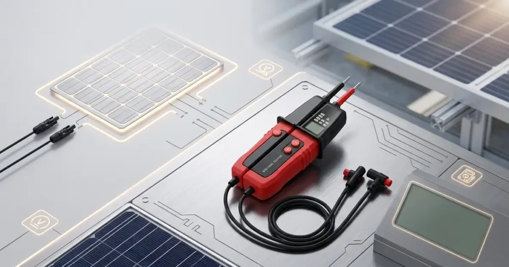
HK235B for Higher-Voltage DC and Solar PV Work
The HK235B adds an LCD and extends its stated range to 1,000V AC and 1,200V DC.
These characteristics can be useful for:
- Checking PV string voltage
- Identifying polarity
- Comparing strings during commissioning
- Building and industrial electrical maintenance
- Continuity and basic resistance checks
- Phase-sequence testing
- RCD testing
PV work requires particular care because DC arcs do not pass through a natural current zero every half-cycle as AC arcs do. An energized PV array can also continue producing voltage whenever sufficient light reaches the modules.
Before using any tester on a PV system, technicians should establish:
- The maximum possible open-circuit voltage under the site’s lowest design temperature
- The tester’s maximum DC voltage
- The applicable CAT rating
- Probe and lead ratings
- Connector and access requirements
- The manufacturer’s permitted test procedure
- The required personal protective equipment
A 1,200V DC display range alone does not automatically make a tester suitable for every PV installation. For systems approaching or exceeding that limit, use equipment specifically rated for the system voltage and test location.
Practical Safety Features to Evaluate
Independent Voltage Indication
For a safety-critical voltage test, determine whether the primary voltage indication works without batteries or with depleted batteries. Battery-powered functions such as the LCD, flashlight, continuity buzzer or vibration alert may behave differently from the basic voltage indication.
This should be clearly stated in the manual and verified during product evaluation.
Audible, Visual and Vibration Feedback
Multiple indication methods can improve usability in:
- Noisy industrial environments
- Dark switch rooms
- Outdoor installations
- Locations where hearing protection is required
- Situations where the display is difficult to view
These feedback methods supplement one another, but the operator must still understand which indication is the safety-related voltage indication.
One-Hand Socket Testing
A probe spacer can help maintain the correct distance between probes for compatible socket outlets. Before treating this as a universal feature, confirm which national socket systems and probe arrangements are supported.
One-hand use should not be interpreted as permission to bypass the manufacturer’s instructions, PPE requirements or safe body positioning.
RCD Trip Testing
An integrated RCD test can support functional checks by applying a test load intended to trip the protective device.
However:
- It does not replace every test performed by a dedicated installation tester.
- The trip-current range must be confirmed.
- The user must understand whether the test checks only tripping or measures trip time and current.
- Both the circuit voltage and RCD type must fall within the tester’s stated scope.
The current Honeytek HK235B product specification lists an RCD test range of 5–50mA at 100–300V. Any different value should be confirmed against the latest datasheet rather than copied from older promotional material.
IP65 Housing
IP65 indicates dust-tight construction and protection against water jets under defined test conditions. It does not mean the tester can be immersed, used in every wet environment or handled without observing electrical safety requirements.
Procurement Checklist for Certified Two-Pole Voltage Testers
Before approving a model, ask the supplier for the following:
Certification
- Current VDE or GS certificate
- Certificate number
- Exact covered model
- Certification-body database entry
- EU Declaration of Conformity
- Applicable EN/IEC standards
- Evidence that the mark has not expired or been withdrawn
Electrical Ratings
- AC and DC voltage ranges
- CAT rating and associated working voltage
- Frequency range
- Basic indication threshold
- Operation with depleted batteries
- RCD test current and voltage range
- Continuity and resistance limits
Mechanical and Environmental Protection
- IP rating
- Operating-temperature range
- Probe-tip protection
- Lead-flex and strain-relief construction
- Drop resistance
- Storage and transport requirements
Documentation and Traceability
- Model and serial or batch identification
- User manual in the target-market language
- Calibration or inspection procedure
- Warranty terms
- Product-change notification process
- Factory quality-control documentation
- Replacement probes or accessories
Sample Evaluation
Before a volume order, evaluate production samples for:
- Display visibility
- Probe accessibility
- Lead flexibility
- Glove usability
- Audible and vibration feedback
- Proving-unit compatibility
- Correct indication with depleted batteries
- RCD-test behavior
- Label durability
- Consistency between the product, manual and certificate
Frequently Asked Questions
Is CE marking the same as VDE or GS certification?
No. CE marking generally represents the manufacturer’s declaration that the product complies with applicable EU legislation. VDE and GS certification involve assessment by an independent certification body.
Is a GS mark mandatory in Germany?
No. The GS mark is voluntary. However, it provides independent confirmation of product safety and can be valuable for employers, distributors and procurement teams.
Can a two-pole tester be used to prove a circuit dead?
A suitably rated two-pole tester may be used as part of an approved safe-isolation procedure. The tester should be checked before and after the test using a proving unit or known live source, subject to applicable national requirements.
Can a non-contact voltage tester prove that a circuit is dead?
It should not be relied upon as the sole instrument for formal absence-of-voltage verification. Non-contact devices are useful for preliminary checks but can produce false positive or false negative indications under certain conditions.
Is the HK235A suitable for a 1,000V DC solar string?
No. Its stated maximum range is 690V AC/DC. Use a tester with an appropriate DC voltage and CAT rating, such as the HK235B where the circuit falls within its documented scope, or another instrument specifically rated for the installation.
Is the HK235B suitable for every 1,200V PV system?
Not automatically. Confirm the maximum PV open-circuit voltage, temperature correction, CAT rating, probe rating and permitted application in the latest manual and certificate.
Does an integrated RCD test replace an installation tester?
No. It can provide a functional trip check, but it may not perform all measurements required for installation verification, such as precise trip time, trip current, loop impedance or insulation resistance.
Conclusion
The value of a professional two-pole voltage tester is not determined by the number of functions printed on its packaging. The most important factors are dependable voltage indication, appropriate electrical ratings, traceable certification and correct use within a documented safe-isolation procedure.
CE marking, GS certification and VDE certification serve different purposes. CE supports regulatory market conformity, while valid GS and VDE marks add independent testing and production-surveillance evidence.
The Honeytek HK235A is positioned for routine building and industrial electrical work within its 690V range. The HK235B adds an LCD, resistance functions and a higher stated DC range for applications including solar PV testing. For either model, professional buyers should verify the current certificate, exact CAT rating, product revision and latest datasheet before procurement.
The practical message echoed by experienced electricians is simple: choose an adequately rated contact tester, understand its limitations, and prove the instrument before and after relying on it.
You might be interested in:
HK68G vs HK78G 2000V PV Digital Multimeter Comparison
How the Honeytek HK588B Clamp Meter Improves HVAC Troubleshooting Efficiency
HK788 & HK789 True RMS Large Current Clamp Meter for Professional Electrical Testing
Small Current Clamp Meter: Definition, Applications,Choose
HK11B+ AC Voltage Detector: The Complete Guide for Electricians and DIY Users
