
Unlike standard resistance measurements, testing Insulation Resistance (IR) involves injecting high voltage (often 500V or 1000V) into a circuit to stress-test the dielectric material. It is one of the most critical tests for maintenance, but because it turns your meter into a voltage source, the safety risks are significantly higher than using a standard digital multimeter (DMM).
This guide outlines the Standard Operating Procedure (SOP) for conducting safe, accurate insulation tests, highlighting the specific capabilities of Honeytek’s Insulation Multimeters.
Phase 1: Pre-Test Safety Preparation (The “Kill” Step)
Trustworthiness (T): Never skip this phase. 90% of accidents happen here.
1. Confirm Total De-energization
- Cut the Power: Disconnect all relevant power sources (inverters, distribution box switches, mains breakers).
- LOTO (Lock Out, Tag Out): Hang a sign reading “Men Working, Do Not Operate” on the switchgear.
- Verify Dead: Before switching your meter to “Insulation” mode, use the standard AC/DC Voltage setting to measure the circuit. The reading must be 0V.
2. Discharge Capacitive Loads
- The Hidden Danger: Long cables, motor windings, and capacitors store energy even after power is cut.
- Action: Use a discharge resistor or a specialized discharge rod to drain energy to the ground. Ensure no residual voltage remains.
3. Select the Right Instrument
- The Standard Meter Trap: A standard multimeter’s “Ohm” (Ω) setting uses only ~3V. It cannot detect insulation failures that only appear under high voltage.
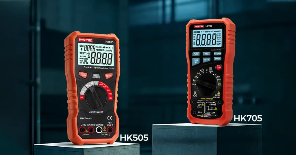
- The Solution: You must use a Megohmmeter or an Insulation Multimeter (like the Honeytek HK505 or HK705).
4. Inspect Leads and Settings
- Self-Check: Verify the meter reads “∞” (Infinity) when open and “0” when leads are shorted.
- Lead Integrity: Ensure test leads have no cracks. Use leads rated for the test voltage (e.g., 1000V CAT III/IV).
Phase 2: Standard Wiring & Testing Procedure
Expertise (E): Correct connection prevents damage to the meter and the technician.
1. Terminal Selection
- L (Line): Connects to the conductor being tested.
- E (Earth): Connects to the ground or chassis.
- G (Guard – Optional): Used on models like the HK4432 series to bypass surface leakage currents for higher precision.
2. The “Earth-First” Connection Rule
To minimize shock risk, always follow this sequence:
- Connect the Black Lead (E) to the Ground/Earth terminal first.
- Connect the Red Lead (L) to the conductor second.
Why? If the Red lead is live and you touch the Black lead while connecting it, you could be shocked.
3. Isolation
Ensure the circuit under test is isolated from other components (lightning arrestors, capacitors, circuit boards). Testing a circuit with these connected will give false readings or damage the components.
Phase 3: The Testing Process (Hands-Off)
Experience (E): Insulation resistance is dynamic. It changes with time and environment.
1. Hands Off
Once the test begins, do not touch the metal probe tips or the equipment. The meter is actively outputting high voltage (e.g., 1000V).
2. The 1-Minute Rule
Do not just take a snapshot reading. Hold the test button for 60 seconds.
- Why? Insulation has “Dielectric Absorption.” The resistance reading usually rises slowly as the material polarizes. The 1-minute reading is the industry standard for accuracy.
3. Choose the Correct Voltage
Follow this general rule to avoid damaging insulation:
- Equipment < 100V: Test at 250V.
- Equipment 100V–500V: Test at 500V.
- Equipment > 500V: Test at 1000V.
4. Environmental Corrections
High humidity and temperature lower resistance readings. If testing in a damp environment, record the conditions. A “fail” in high humidity might be a “pass” once dried out.
Phase 4: Post-Test Safety (The “Discharge” Step)
Authoritativeness (A): The test isn’t over when you release the button.
1. Wait for Auto-Discharge
Do not disconnect the leads immediately. Modern Honeytek testers (like the HK4432D) have an Auto-Discharge function. Watch the screen; voltage will drop rapidly. Wait until it reads <30V.
2. Verification
For large capacitive loads (long cables), double-check with a voltage tester to ensure the “ghost voltage” is gone before touching the terminals.
3. Disconnect in Reverse
- Disconnect the Red Lead (L) first.
- Disconnect the Black Lead (E) last.
Phase 5: Common Fatal Mistakes to Avoid
- Testing Live Circuits: Applying an insulation test to a live line will likely blow the meter’s fuse or cause an arc flash. Always verify 0V first.
- Using Standard Ohms: Do not write “Insulation OK” based on a standard multimeter reading. It is negligent and dangerous.
- Wrong Voltage Selection: Testing a 24V data cable with 1000V will fry the electronics. Testing a 1000V solar string with 250V will miss potential faults.
- Touching Before Discharge: The most common injury comes from touching the cable immediately after testing, acting as the ground path for the stored charge.
Phase 6: Quick Field Workflow (For Solar/PV Sites)
A simplified checklist for your Job Safety Analysis (JSA).
- Isolate: Open AC/DC disconnects. LOTO the switchgear.
- Verify: Use a DMM Voltage mode to confirm 0V on the string.
- Select: Set Honeytek meter to Insulation Mode (e.g., 1000V for a 600V system).
- Connect: Clip Black lead to Racking/Ground. Clip Red lead to Shorted PV Positive/Negative.
- Test: Press and lock the “Test” button. Wait 1 minute. Record value.
- Discharge: Release button. Wait for display voltage to drop to zero.
- Disconnect: Remove Red lead, then Black lead.
Recommended Gear: Honeytek Insulation Series
To perform these tests safely, you need equipment rated for the job. Honeytek offers a range of high-precision instruments.
1. Honeytek HK505 / HK705 (Insulation Multimeters)
- Best For: HVAC technicians and General Electricians.
- Features: Combines a full True-RMS Multimeter with an Insulation Tester. No need to carry two meters.
- Specs: Test voltages up to 1000V, Auto-discharge, Live circuit detection.
2. Honeytek HK4432 Series (Portable Insulation Testers)
- Best For: Industrial maintenance, Solar Farms, and High-Voltage Cable testing.
- Features:
- HK4432C: Digital precision with analog bar graph.
- High Range: Measures up to Giga-Ohms (GΩ).
- External Power: Support for extended testing sessions.
FAQ: Frequently Asked Questions
Q1: Can I use the HK505 to test a live circuit?
A: No. Insulation resistance testing is a “dead test.” The circuit must be de-energized. However, the HK505 has built-in protection that alerts you if it detects voltage on the line before the test starts.
Q2: What is the minimum acceptable resistance value?
A: A general rule of thumb is 1 MΩ per 1000V of operating voltage, with a 1 MΩ absolute minimum. However, for modern equipment, values are typically in the 100 MΩ to GΩ range.
Q3: Why use the “G” (Guard) terminal on the HK4432?
A: The G terminal is used to divert surface leakage current away from the measurement circuit. This is critical when testing dirty or wet cables to get an accurate reading of the internal insulation resistance.
Q4: How does the “Auto-Discharge” feature work?
A: After the test, the cable acts like a charged battery. The Honeytek meter internally connects a resistor across the terminals to safely drain this energy so it doesn’t shock you when you disconnect the leads.
Partner with Honeytek
Looking for Professional Test Instruments?
Honeytek is a leading manufacturer of Digital Multimeters, Clamp Meters, and Insulation Testers. We are committed to safety, precision, and durability.
- Global Distribution: We are actively recruiting agents worldwide.
- OEM/ODM Services: We provide full customization for your brand, from housing color to firmware features.
[👉 Contact Our Sales Team for an OEM Quote]
[📥 Download the HK4432 Series Datasheet]
You May Also Be Interested In:
