
Introduction
Solar photovoltaic (PV) systems are generally reliable, but faults still occur due to installation errors, environmental conditions, or component degradation. For installers and maintenance teams, the challenge is not just identifying faults, but doing so quickly and accurately under live conditions.
This is where a PV clamp meter becomes essential. Unlike traditional tools, it allows non-contact current measurement and supports high-voltage testing, making it a practical choice for modern solar systems.
This guide outlines a structured troubleshooting approach using a PV clamp meter, helping professionals reduce downtime and improve diagnostic accuracy.

Why a PV Clamp Meter is Essential for Troubleshooting
A PV clamp meter is designed to handle the realities of solar installations: high DC voltage, long cable runs, and parallel string configurations.
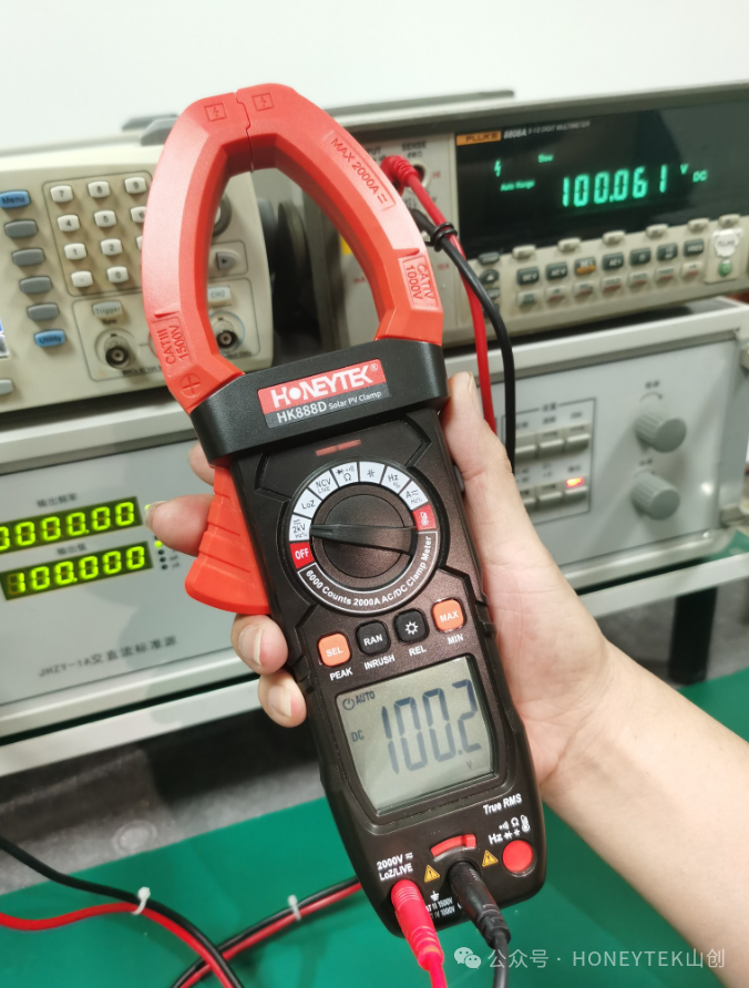
It enables technicians to measure current without disconnecting circuits, which is critical for live system diagnostics. When combined with features like True RMS, LoZ (Low Impedance), and high voltage capability, it becomes a reliable tool for identifying faults in complex PV systems.
For busy installers and tool distributors, understanding these capabilities helps ensure the right tool is used for the right task.
Step-by-Step PV System Troubleshooting Process
Step 1: Check DC Voltage at String Level
Start by measuring the DC voltage of each string using test leads. Compare the measured value with the system’s expected voltage based on design specifications.
If the voltage is significantly lower than expected, it may indicate issues such as damaged panels, loose connections, or partial shading. Voltage measurement provides the first indication of whether the system is operating within normal parameters.
Step 2: Measure Current with a PV Clamp Meter
Next, use a PV clamp meter to measure the current of each string. Clamp around a single conductor—either positive or negative—to obtain accurate readings.
Comparing current values across strings helps identify underperforming sections. Lower current in one string typically indicates shading, module degradation, or a faulty connection.
Step 3: Compare MPPT Inputs
Modern inverters use multiple Maximum Power Point Tracking (MPPT) inputs. Each MPPT channel should show consistent voltage and current behavior.
By comparing MPPT inputs, technicians can quickly detect imbalance between strings. Uneven readings often point to inefficiencies or faults that require further investigation.
Step 4: Inspect Wiring and Connections
After electrical measurements, perform a physical inspection of the system. Check for loose terminals, damaged cables, or signs of corrosion.
In many cases, performance issues are caused not by components but by connection quality and installation conditions. A systematic inspection helps confirm whether the issue is electrical or mechanical.
Common PV System Problems and Their Causes
| Problem | Possible Cause |
|---|---|
| Low current | Shading, panel degradation, or faulty module |
| Voltage drop | Cable loss, loose connection, or poor installation |
| No output | Open circuit or disconnected string |
| Fluctuating readings | Ghost voltage or electrical interference |
Understanding these patterns allows installers to move from measurement to diagnosis more efficiently. A PV clamp meter plays a key role in identifying these conditions in real time.
The Role of LoZ in PV Troubleshooting
One common challenge in solar systems is ghost voltage, which can lead to incorrect readings and misdiagnosis. This is especially prevalent in installations with long cable runs and parallel wiring.
A PV clamp meter with LoZ (Low Impedance) function helps eliminate these false signals by reducing input impedance. This ensures that voltage readings reflect actual system conditions rather than induced or capacitive voltages.
For troubleshooting, this means fewer false positives and more reliable decision-making.
Best Practices for Accurate Measurement
Use the Correct Measurement Mode
Ensure the clamp meter is set to the appropriate mode (DC or AC) before taking measurements. Incorrect settings can lead to misleading results.
Measure One Conductor at a Time
When measuring current, clamp only one conductor. Clamping both positive and negative cables will result in zero reading due to magnetic field cancellation.
Compare Data, Not Just Individual Values
Always compare readings across strings or MPPT inputs. Relative differences often reveal more than absolute values.
Consider Environmental Factors
Temperature, shading, and system load conditions can all affect readings. Measurements should be interpreted within the context of real operating conditions.
Choosing the Right PV Clamp Meter
For effective troubleshooting, a PV clamp meter should include:
- High DC voltage capability (1500V–2000V)
- High current measurement range (1000A+)
- True RMS for accurate waveform analysis
- LoZ function for eliminating ghost voltage
- Additional features such as inrush current and peak hold
Manufacturers such as Honeytek, known for clamp meters and digital multimeters, focus on integrating these features to support real-world photovoltaic testing scenarios.
FAQ
What is the first step in PV system troubleshooting?
The first step is always to measure DC voltage at the string level. This helps determine whether the system is operating within expected parameters and provides a baseline for further analysis.
Why is current comparison between strings important?
Comparing current across strings helps identify underperforming sections. Differences in current often indicate shading, faulty modules, or connection issues.
Can faults be detected without shutting down the system?
Yes. A PV clamp meter allows live measurement of current, enabling technicians to diagnose issues without interrupting system operation.
How does LoZ improve troubleshooting accuracy?
LoZ eliminates ghost voltage caused by induced signals in long cables, ensuring that voltage readings represent actual electrical conditions.
Is a standard multimeter sufficient for PV troubleshooting?
A multimeter is useful for certain measurements, but it cannot safely or efficiently measure high current in live systems. A PV clamp meter is more suitable for field diagnostics.
Conclusion
Effective PV system troubleshooting requires a combination of structured methodology and the right measurement tools. As solar systems become more complex and operate at higher voltages, the role of the PV clamp meter becomes increasingly important.
By following a systematic approach—checking voltage, measuring current, comparing MPPT inputs, and inspecting wiring—technicians can identify faults quickly and accurately.
You might be interested in:
- HK888E 2000A 2000V AC/DC Solar PV Clamp Meter
- HK78G 2000V TRMS Auto Range Digital Multimeter for PV solar
- HK888D 6000 Count TRMS 2000A AC/DC Solar PV Clamp Meter
- HK78B+ 2000 Counts TRMS Manual Range Digital Multimeter
