
Measuring DC current in a photovoltaic (PV) system is a routine but critical task during installation, commissioning, and ongoing maintenance. Unlike traditional inline measurements, a DC clamp meter allows you to measure current safely without disconnecting the circuit, making it the preferred tool for live PV systems.
This guide explains how to correctly measure DC current in PV systems, what to watch out for, and how to obtain reliable results in real-world solar applications.
Understanding the Principle
In a PV system, DC current is measured by clamping a DC-capable clamp meter around a single DC conductor. The meter uses a Hall-effect sensor to detect the magnetic field generated by the current flow and converts it into a current reading.
Key point: Only clamp one conductor (positive or negative), never both.
Instrument Requirements and Safety Considerations
Use a Clamp Meter That Supports DC Current
Not all clamp meters can measure DC current. Many basic or older models support AC current only and will read zero on PV circuits.
You must use a clamp meter that:
- Explicitly supports DC current (A⎓)
- Uses Hall-effect sensing
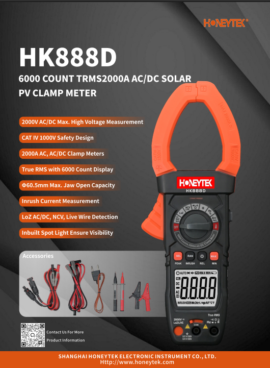
For PV professionals, a dedicated Solar Clamp Meter is strongly recommended.
Verify CAT Rating for PV Systems
PV systems often operate at high DC voltages:
- Residential & commercial: 600–1000 V DC
- Utility-scale & modern systems: up to 1500 V DC
Your clamp meter should meet at least one of the following:
- CAT III 1000 V
- CAT IV 600 V
- Or CAT III 1500 V DC (PV-rated)
Using an under-rated meter in a PV environment poses serious safety risks.
Confirm the Current Range
Ensure the clamp meter’s DC current range exceeds:
- Individual string current (typically 8–15 A per string)
- Combiner or main DC output current (often tens to hundreds of amps)
Step-by-Step: Measuring DC Current on the PV DC Side
Preparation Before Measurement
- Confirm the meter’s voltage and current ratings match the PV system
- Remove all test leads — use the clamp only
- Wear appropriate PPE: insulated gloves, safety glasses
- Work in a dry, stable environment and follow local PV safety codes
Set the Meter to DC Current and Zero It
- Turn the rotary switch to DC current (A⎓)
- Some models require selecting current first, then switching AC/DC via a button
- With the clamp fully closed and no conductor inside, wait for the display to stabilize
- Press ZERO / REL to eliminate Hall sensor offset
This zeroing step is essential for accurate DC measurements.
Clamp a Single PV Conductor Correctly
- Locate the PV string cable inside the combiner box or near the array output
- Clamp only one conductor (positive or negative)
- Never clamp both conductors together — their magnetic fields cancel out
- Position the cable at the center of the clamp jaw
- Ensure the clamp jaw is fully closed
Read and Record the Current
- Measure while the system is operating under normal irradiance
- Wait for the reading to stabilize
- If the display shows a negative value, simply reverse the clamp orientation
(Polarity affects direction, not accuracy)
For multi-string systems, measure each string individually and record the results.
Common PV Measurement Scenarios
PV String Current Verification
Measure each string at the combiner box to:
- Identify shaded strings
- Detect failed or degraded modules
- Spot wiring or connector issues
A string with significantly lower current than others under similar conditions is a red flag.
Combiner Box Output Current
Clamp the main positive or negative output conductor to:
- Verify total DC current
- Cross-check inverter input readings
- Compare actual output with design calculations
Maintenance and Fault Diagnosis
Typical findings include:
- 0 A on a string → blown fuse, open circuit, reversed polarity
- Consistently lower current → partial shading, module degradation
- Irregular readings over time → connector heating or intermittent faults
Tracking current values over time is an effective way to assess PV system health.
Accuracy and Safety Best Practices
Choose a True RMS AC+DC Clamp Meter
PV sites often involve both DC (array side) and AC (inverter output).
A True RMS AC+DC clamp meter allows one instrument to handle both accurately.
Minimize Magnetic Interference
- Avoid clamping near tightly bundled conductors
- Separate the target cable from nearby high-current lines if possible
- Keep distance from busbars and inverter DC terminals
Improve Accuracy at Low Current Levels
- Take multiple readings and average them
- Use a higher-resolution PV clamp meter if available
- Avoid measuring near the lower limit of the meter’s range
High-Voltage PV Systems (1000–1500 V DC)
For modern high-voltage systems:
- Maintain proper safety clearances
- Use PV-rated clamp meters with slim jaws
- Combine current measurement with voltage and irradiance data for full system evaluation
Best Practice for Measuring DC Current in PV Systems
To measure DC current in a photovoltaic system safely and accurately:
- Select the right clamp meter (DC-capable, sufficient CAT rating)
- Zero the meter before measurement
- Clamp only one DC conductor
- Measure under normal operating conditions
- Follow PV-specific safety procedures
When done correctly, clamp meters provide a fast, non-intrusive, and reliable method for PV system commissioning, routine inspection, and fault diagnosis—without ever breaking the circuit.
Honeytek designs and manufactures digital multimeters and DC clamp meters engineered for solar installation, commissioning, and maintenance.
Explore our PV-ready clamp meters or contact our team to discuss your application.
You May Also Be Interested In:
- AC-Only vs. AC/DC Clamp Meters: Choosing the Right Tool for Your Electrical Applications
- Why Handheld Capacitance Meters Struggle With Small-Capacitor Measurements
- Portable Capacitance Meter vs. LCR Meter: What’s the Real Difference?
- How to Measure DC Current with Clamp Meter
- True RMS Industrial Digital Multimeters: Why They Matter in Modern Electrical Systems
